Κυριακή 31 Οκτωβρίου 2010

Runway [ΕΝ]

 
Helsinki-Vantaa Airport, runway 33
A runway (RWY) is a strip of land at an airport on which aircraft can take off and land and forms part of the maneuvering area. Runways may be a man-made surface (often asphalt, concrete, or a mixture of both) or a natural surface (grass, dirt, gravel, ice, or salt).
By extension, the term has also come to mean any long, flat, straight area, such as that used in fashion shows.


Orientation and dimensions
Runways are named by a number between 01 and 36, which is generally one tenth of the magnetic azimuth of the runway's heading: a runway numbered 09 points east (90°), runway 18 is south (180°), runway 27 points west (270°) and runway 36 points to the north (360° rather than 0°). However, runways in North America that lie within the Northern Domestic Airspace are numbered relative to true north because proximity to the magnetic North Pole makes the magnetic declination large. A runway can normally be used in both directions, and is named for each direction separately: e.g., "runway 33" in one direction is "runway 15" when used in the other. The two numbers always differ by 18 (= 180°).

El Dorado International Airport, Runway 31R/13L


If there is more than one runway pointing in the same direction (parallel runways), each runway is identified by appending Left (L), Center (C) and Right (R) to the number — for example, Runways One Five Left (15L), One Five Center (15C), and One Five Right (15R). Runway Zero Three Left (03L) becomes Runway Two One Right (21R) when used in the opposite direction (derived from adding 18 to the original number for the 180 degrees when approaching from the opposite direction).
At large airports with more than three parallel runways (for example, at Los Angeles, Detroit Metropolitan Wayne County, Hartsfield-Jackson Atlanta, Denver, and Dallas-Fort Worth), some runway identifiers are shifted by 10 degrees to avoid the ambiguity that would result with more than three parallel runways. For example, in Los Angeles, this system results in Runways 6L, 6R, 7L, and 7R, even though all four runways are exactly parallel (approximately 69 degrees). At Dallas-Fort Worth, there are five parallel runways, named 17L, 17C, 17R, 18L, and 18R, all oriented at a heading of 175.4 degrees.
For clarity in radio communications, each digit in the runway name is pronounced individually: runway three six, runway one four, etc. A leading zero, for example in "runway zero six" or "runway zero one left", is included for International Civil Aviation Organization (ICAO) and some United States military airports (such as Edwards Air Force Base). However in the United States at most civil aviation airports, the leading zero is often dropped. This also includes some military airfields such as Cairns Army Airfield. This American anomaly may lead to inconsistencies in conversations between American pilots and controllers in other countries. It is very common in a country such as Canada for a controller to clear an incoming American aircraft to, for example, Runway 04, and the pilot read back the clearance as Runway 4. In flight simulation programs those of American origin might apply U.S. usage to airports around the world. For example Runway 05 at Halifax will appear on the program as the single digit 5 rather than 05.
Runway designations change over time because the magnetic poles slowly drift on the Earth's surface and the magnetic bearing will change. Depending on the airport location and how much drift takes place, it may be necessary over time to change the runway designation. As runways are designated with headings rounded to the nearest 10 degrees, this will affect some runways more than others. For example, if the magnetic heading of a runway is 233 degrees, it would be designated Runway 23. If the magnetic heading changed downwards by 5 degrees to 228, the Runway would still be Runway 23. If on the other hand the original magnetic heading was 226 (Runway 23), and the heading decreased by only 2 degrees to 224, the runway should become Runway 22. Because the drift itself is quite slow, runway designation changes are uncommon, and not welcomed, as they require an accompanying change in aeronautical charts and descriptive documents. When runway designations do change, especially at major airports, it is often changed overnight as taxiway signs need to be changed and the huge numbers at each end of the runway need to be repainted to the new runway designators. In July 2009 for example, London Stansted Airport in the United Kingdom changed its runway designations from 05/23 to 04/22 overnight.
For fixed-wing aircraft it is advantageous to perform take-offs and landings into the wind to reduce takeoff roll and reduce the ground speed needed to attain flying speed. Larger airports usually have several runways in different directions, so that one can be selected that is most nearly aligned with the wind. Airports with one runway are often constructed to be aligned with the prevailing wind.
Runway dimensions vary from as small as 245 m (804 ft) long and 8 m (26 ft) wide in smaller general aviation airports, to 5,500 m (18,045 ft) long and 80 m (262 ft) wide at large international airports built to accommodate the largest jets, to the huge 11,917 m (39,098 ft) x 274 m (899 ft) lake bed runway 17/35 at Edwards Air Force Base in California - a landing site for the Space Shuttle.


Placement and grouping

Two runways pointing in the same direction are classed as dual or parallel runways depending on the separation distance. In some countries, flight rules mandate that only one runway may be used at a time under certain conditions (usually adverse weather) if the parallel runways are too close to each other.

Declared distances


TORA
Takeoff Run Available - The length of runway declared available and suitable for the ground run of an airplane taking off.
TODA
Takeoff Distance Available - The length of the takeoff run available plus the length of the clearway, if clearway is provided.
(The clearway length allowed must lie within the aerodrome or airport boundary. According to the Federal Aviation Regulations and Joint Aviation Requirements (JAR) TODA is the lesser of TORA plus clearway or 1.5 times TORA).
ASDA
Accelerate-Stop Distance Available - The length of the takeoff run available plus the length of the stopway, if stopway is provided.
LDA
Landing Distance Available - The length of runway which is declared available and suitable for the ground run of an airplane landing.
EDA
Emergency Distance Available - LDA (or TORA) plus a stopway.

Sections of a runway


  • The Runway Safety Area is the cleared, smoothed and graded area around the paved runway. It is kept free from any obstacles that might impede flight or ground roll of aircraft.
  • The Runway is the surface from threshold to threshold, which typically features threshold markings, numbers, centerlines, but not overrun areas at both ends.
  • Blast pads, also known as overrun areas or stopways, are often constructed just before the start of a runway where jet blast produced by large planes during the takeoff roll could otherwise erode the ground and eventually damage the runway. Overrun areas are also constructed at the end of runways as emergency space to slowly stop planes that overrun the runway on a landing gone wrong, or to slowly stop a plane on a rejected takeoff or a take-off gone wrong. Blast pads are often not as strong as the main paved surface of the runway and are marked with yellow chevrons. Planes are not allowed to taxi, take-off or land on blast pads, except in an emergency.
Runway diagram, Blast pad.png
  • Displaced thresholds may be used for taxiing, takeoff, and landing rollout, but not for touchdown. A displaced threshold often exists because obstacles just before the runway, runway strength, or noise restrictions may make the beginning section of runway unsuitable for landings. It is marked with white paint arrows that lead up to the beginning of the landing portion of the runway.
Runway diagram, Displaced threshold.png


Runway lighting

History

The first runway lighting appeared in 1930 at Cleveland Municipal Airport (now known as Cleveland Hopkins International Airport) in Cleveland, Ohio. A line of lights on an airfield or elsewhere to guide aircraft in taking off or coming in to land or an illuminated runway is sometimes also known as a flare path.


Technical specifications

Runway lighting is used at airports which allow night landings. Seen from the air, runway lights form an outline of the runway. A particular runway may have some or all of the following.
  • Runway End Identification Lights (REIL) – unidirectional (facing approach direction) or omnidirectional pair of synchronized flashing lights installed at the runway threshold, one on each side.
  • Runway end lights – a pair of four lights on each side of the runway on precision instrument runways, these lights extend along the full width of the runway. These lights show green when viewed by approaching aircraft and red when seen from the runway.
  • Runway edge lights – white elevated lights that run the length of the runway on either side. On precision instrument runways, the edge-lighting becomes yellow in the last 2,000 ft (610 m) of the runway. Taxiways are differentiated by being bordered by blue lights, or by having green centre lights, depending on the width of the taxiway, and the complexity of the taxi pattern.
  • Runway Centerline Lighting System (RCLS) – lights embedded into the surface of the runway at 50 ft (15 m) intervals along the runway centerline on some precision instrument runways. White except the last 3,000 ft (914 m), alternate white and red for next 2,000 ft (610 m) and red for last 1,000 ft (305 m).
  • Touchdown Zone Lights (TDZL) – rows of white light bars (with three in each row) on either side of the centerline over the first 3,000 ft (914 m) (or to the midpoint, whichever is less) of the runway.
  • Taxiway Centerline Lead-Off Lights – installed along lead-off markings, alternate green and yellow lights embedded into the runway pavement. It starts with green light about runway centerline to the position of first centerline light beyond holding position on taxiway.
  • Taxiway Centerline Lead-On Lights – installed the same way as taxiway centerline lead-off Lights.
  • Land and Hold Short Lights – a row of white pulsating lights installed across the runway to indicate hold short position on some runways which are facilitating land and hold short operations (LAHSO).
  • Approach Lighting System (ALS) – a lighting system installed on the approach end of an airport runway and consists of a series of lightbars, strobe lights, or a combination of the two that extends outward from the runway end.
According to Transport Canada's regulations, the runway-edge lighting must be visible for at least 2 mi (3 km). Additionally, a new system of advisory lighting, Runway Status Lights, is currently being tested in the United States.
The edge lights must be arranged such that:
  • the minimum distance between lines is 75 ft (23 m), and maximum is 200 ft (61 m);
  • the maximum distance between lights within each line is 200 ft (61 m);
  • the minimum length of parallel lines is 1,400 ft (427 m);
  • the minimum number of lights in the line is 8.
Control of Lighting System Typically the lights are controlled by a control tower, a Flight Service Station or another designated authority. Some airports/airfields (particularly uncontrolled ones) are equipped with Pilot Controlled Lighting, so that pilots can temporarily turn on the lights when the relevant authority is not available. This avoids the need for automatic systems or staff to turn the lights on at night or in other low visibility situations. This also avoids the cost of having the lighting system on for extended periods. Smaller airports may not have lighted runways or runway markings. Particularly at private airfields for light planes, there may be nothing more than a windsock beside a landing strip.


Runway markings

There are runway markings and signs on any runway. Larger runways have a distance remaining sign (black box with white numbers). This sign uses a single number to indicate the thousands of feet remaining, so 7 will indicate 7,000 ft (2,134 m) remaining. The runway threshold is marked by a line of green lights.
RunwayDiagram.png
There are three types of runways:
  • visual Runways are used at small airstrips and are usually just a strip of grass, gravel, asphalt or concrete. Although there are usually no markings on a visual runway, they may have threshold markings, designators, and centerlines. Additionally, they do not provide an instrument-based landing procedure; pilots must be able to see the runway to use it. Also, radio communication may not be available and pilots must be self-reliant.
  • non-precision instrument runways are often used at small- to medium-size airports. These runways, depending on the surface, may be marked with threshold markings, designators, centerlines, and sometimes a 1,000 ft (305 m) mark (known as an aiming point, sometimes installed at 1,500 ft (457 m)). They provide horizontal position guidance to planes on instrument approach via Non-directional beacon (NDB), VHF omnidirectional range (VOR), Global Positioning System, etc.
  • precision instrument runways, which are found at medium- and large-size airports, consist of a blast pad/stopway (optional, for airports handling jets), threshold, designator, centerline, aiming point, and 500 ft (152 m), 1,000 ft (305 m)/1,500 ft (457 m), 2,000 ft (610 m), 2,500 ft (762 m), and 3,000 ft (914 m) touchdown zone marks. Precision runways provide both horizontal and vertical guidance for instrument approaches.

National variants

  • In Australia, Canada, Japan, the United Kingdom, as well as some other countries all 3-stripe and 2-stripe touchdown zones for precision runways are replaced with one-stripe touchdown zones.
  • In Australia, precision runways consist of only an aiming point and one 1-stripe touchdown zone. Furthermore, many non-precision and visual runways lack an aiming point.
  • In some Latin American countries like Colombia, Ecuador and Peru one 3-stripe is added and a 2-stripe is replaced with the aiming point .
  • Some European countries replace the aiming point with a 3-stripe touchdown zone.
  • Runways in Norway have yellow markings instead of the usual white ones. This also occurs on some airports in Japan. The yellow markings are used to ensure better contrast against snow.
  • Runways may have different types on each end. To cut costs, many airports do not install precision guidance equipment on both ends. Runways with one precision end and any other type of end can install the full set of touchdown zones, even if some are past the midpoint. If a runway has precision markings on both ends, touchdown zones within 900 ft (274 m) of the midpoint are omitted, to avoid pilot confusion over which end the marking belongs to.

Runway safety

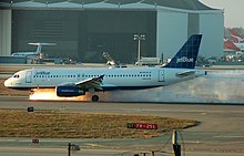
Runway excursion is an incident involving only a single aircraft where it makes an inappropriate exit from the runway. This can happen because of pilot error, poor weather, emergency, or a fault with the aircraft. Overrun is a type of excursion where the aircraft is unable to stop before the end of the runway. An example of such an event is Air France Flight 358 in 2005. Further examples can be found in the overruns category. Runway excursion is the most frequent type of landing accident, slightly ahead of runway incursion. For runway accidents recorded between 1995 and 2007, 96% were of the 'excursion' type.
Runway event is another term for a runway accident.
Runway incursion involves a first aircraft, as well as a second aircraft, vehicle, or person. It is defined by the U.S. Federal Aviation Administration (FAA) as: "Any occurrence at an aerodrome involving the incorrect presence of an aircraft, vehicle or person on the protected area of a surface designated for the landing and take off of aircraft."
Runway confusion involves a single aircraft, and is used to describe the error when the aircraft makes "the unintentional use of the wrong runway, or a taxiway, for landing or take-off".
The U.S. FAA publishes an annual report on runway safety issues, available from the FAA website. New systems designed to improve runway safety, such as Airport Movement Area Safety System (AMASS) and Runway Awareness and Advisory System (RAAS), are discussed in the report. AMASS prevented the serious near-collision in the 2007 San Francisco International Airport runway incursion.
Runway condition is also an important parameter related to meteorological conditions and air safety.
  • Dry: the surface of the runway is clear of water, snow or ice.
  • Damp: change of color on the surface due to moisture.
  • Wet: the surface of the runway is soaked but there is no significant patches of standing water.
  • Water patches: patches of standing water are visible.
  • Flooded: there is extensive standing water.
According to the JAR definition, a runway with water patches or that is flooded is considered to be contaminated.


Pavement

The choice of material used to construct the runway depends on the use and the local ground conditions. For a major airport, where the ground conditions permit, the most satisfactory type of pavement for long-term minimum maintenance is concrete. Although certain airports have used reinforcement in concrete pavements, this is generally found to be unnecessary, with the exception of expansion joints across the runway where a dowel assembly, which permits relative movement of the concrete slabs, is placed in the concrete. Where it can be anticipated that major settlements of the runway will occur over the years because of unstable ground conditions, it is preferable to install asphaltic concrete surface, as it is easier to patch on a periodic basis. For fields with very low traffic of light planes, it is possible to use a sod surface. Some runways also make use of salt flat runways.
For pavement designs, borings are taken to determine the subgrade condition, and based on the relative bearing capacity of the subgrade, the specifications are established. For heavy-duty commercial aircraft, the pavement thickness, no matter what the top surface, varies from 10 in (250 mm) to 4 ft (1 m), including subgrade.
Airport pavements have been designed by two methods. The first, Westergaard, is based on the assumption that the pavement is an elastic plate supported on a heavy fluid base with a uniform reaction coefficient known as the K value. Experience has shown that the K values on which the formula was developed are not applicable for newer aircraft with very large footprint pressures.
The second method is called the California bearing ratio and was developed in the late 1940s. It is an extrapolation of the original test results, which are not applicable to modern aircraft pavements or to modern aircraft landing gear. Some designs were made by a mixture of these two design theories.
A more recent method is an analytical system based on the introduction of vehicle response as an important design parameter. Essentially it takes into account all factors, including the traffic conditions, service life, materials used in the construction, and, especially important, the dynamic response of the vehicles using the landing area.
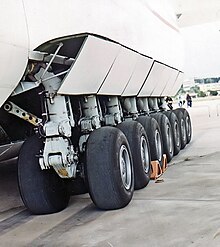
Because airport pavement construction is so expensive, every effort is made to minimize the stresses imparted to the pavement by aircraft. Manufacturers of the larger planes design landing gear so that the weight of the plane is supported on larger and more numerous tires. Attention is also paid to the characteristics of the landing gear itself, so that adverse effects on the pavement are minimized. Sometimes it is possible to reinforce a pavement for higher loading by applying an overlay of asphaltic concrete or portland cement concrete that is bonded to the original slab.
Post-tensioning concrete has been developed for the runway surface. This permits the use of thinner pavements and should result in longer concrete pavement life. Because of the susceptibility of thinner pavements to frost heave, this process is generally applicable only where there is no appreciable frost action.


Pavement surface

Runway pavement surface is prepared and maintained to maximize friction for wheel braking. To minimize hydroplaning following heavy rain, the pavement surface is usually grooved so that the surface water film flows into the grooves and the peaks between grooves will still be in contact with the aircraft tires. To maintain the macrotexturing built into the runway by the grooves, maintenance crews engage in airfield rubber removal or hydrocleaning in order to meet required FAA friction levels.


Surface Type Codes

In aviation charts, the surface type is usually abbreviated to a three-letter code.
The most common hard surface types are Asphalt and Concrete. The most common soft surface types are Grass and Gravel.
  • ASP: Asphalt
  • BIT: Bitumenous Asphalt or Tarmac
  • BRI: Bricks (no longer in use, covered with Asphalt or Concrete now)
  • CLA: Clay
  • COM: Composite
  • CON: Concrete
  • COP: Composite
  • GRS: Grass or earth not graded or rolled
  • COR: Coral (Coral reef structures)
  • GRE: Graded or rolled earth, Grass on graded earth
  • GVL: Gravel
  • LAT: Laterite
  • ICE: Ice
  • MAC: Macadam
  • PEM: Partially Concrete, Asphalt or Bitumen-bound Macadam
  • PER: Permanent Surface, Details unknown
  • PSP: Marsden Matting (Derived from Pierced/Perforated Steel Planking)
  • SAN: Sand
  • SNO: Snow
  • U: Unknown surface
Water runways do not have a type code as they dont have physical markings, and are thus not registered as specific runways.


Active runway

The active runway is the runway at an airport that is in use for takeoffs and landings. Since takeoffs and landings are usually done as close to "into the wind" as possible, wind direction generally determines the active runway (or just the active in aviation vernacular).
Selection of the active runway, however, depends on a number of factors. At a non-towered airport, pilots usually select the runway most nearly aligned with the wind, but they are not obliged to use that particular runway. For example, a pilot arriving from the east may elect to land straight in to an east-west runway despite a minor tailwind or significant crosswind, in order to expedite his arrival, although it is recommended to always fly a regular traffic pattern to more safely merge with other aircraft.
At controlled airports, the active is usually determined by a tower supervisor. However, there may be constraints, such as policy from the airport manager (calm wind runway selection, for example, or noise abatement guidelines) that dictate an active runway selection that is not the one most nearly aligned with the wind.
At major airports with multiple runways, the active could be any of a number of runways. For example, when O'Hare (ORD) is landing on 27L and 32L, departures use 28 and 32R, thus making four active runways. When they are landing on 14R and 22R, departures use 22L and 9R, and occasionally a third arrival runway, 14L, will be employed, bringing the active runway count to five.
At major airports, the active runway is based on weather conditions (visibility and ceiling, as well as wind, and runway conditions such as wet/dry or snow covered), efficiency (ORD can land more aircraft on 14R/32L than they can on 9R/27L), traffic demand (when a heavy departure rush is scheduled, a runway configuration that optimizes departures vs arrivals may be desirable), and time of day (ORD is obliged to use runway 9R/27L during the hours of roughly midnight to 6 a.m. due to noise abatement).
London Heathrow Airport in the United Kingdom has two runways which are parallel to each other, they are designated 09L/27R and 09R/27L. They are used in segregated alternate mode which means one runway is used only for arrivals and the other is only used for departures. The present pattern provides for one runway to be used by landing aircraft from 06:00 until 15:00 and then arrivals will switch to the other runway from 15:00 until after the last departure, after which landing aircraft use the first runway again until 06:00. However, on Sunday each week the runway used before midnight continues to be used for landings until 06:00. This means early morning arrivals before 06:00 use a different runway on successive weeks and that the runways used by landing aircraft before and after 15:00 also alternate on a weekly basis. This only applies to westerly operations as landing aircraft always use runway 09L.


Runway length

At sea level, 10,000 ft (3,000 m) can be considered an adequate length to land virtually any aircraft. For example, at O'Hare International, when landing simultaneously on 22R and 28 or parallel 27L, it is routine for arrivals from the Far East which would normally be vectored for 22R (7,500 ft (2,286 m)) or 27L (7,967 ft (2,428 m)) to request 28 (13,001 ft (3,963 m)). It is always accommodated, although occasionally with a delay. Another example is that the Luleå Airport in Sweden was extended to 10,990 ft (3,350 m) to allow any fully loaded freight aircraft to take off.
An aircraft will need a longer runway at a higher altitude due to decreased density of air at higher altitudes, which reduces lift and engine power. An aircraft will also require a longer runway in hotter or more humid conditions. Most commercial aircraft carry manufacturer's tables showing the adjustments required for a given temperature.

Σάββατο 30 Οκτωβρίου 2010

Air safety [EN]

Navigation aids and instrument flight


One of the first navigation aids to be introduced (in the USA in the late 1920s) was airfield lighting to assist pilots to make landings in poor weather or after dark. The Precision Approach Path Indicator was developed from this in the 1930s, indicating to the pilot the angle of descent to the airfield. This later became adopted internationally through the standards of the International Civil Aviation Organization (ICAO).
In 1929 Jimmy Doolittle developed instrument flight.
With the spread of radio technology, several experimental radio based navigation aids were developed from the late 1920s onwards. These were most successfully used in conjunction with instruments in the cockpit in the form of Instrument landing systems (ILS), first used by a scheduled flight to make a landing in a snowstorm at Pittsburgh in 1938. A form of ILS was adopted by the ICAO for international use in 1949.
Following the development of radar in World War II, it was deployed as a landing aid for civil aviation in the form of Ground-controlled approach (GCA) systems, joined in 1948 by distance measuring equipment (DME), and in the 1950s by airport surveillance radar as an aid to air traffic control. VHF omnidirectional range (VOR) stations became the predominate means of route navigation during the 1960s, superseding the low frequency radio ranges and the Non-directional beacon (NDB). The ground based VOR stations were often co-located with DME transmitters and then labeled as VOR-DME stations on navigation charts. VORTAC stations, which combined VOR and TACAN features (military TACtical Air Navigation) — the latter including both a DME distance feature and a separate TACAN azimuth feature, which provides military pilots data similar to the civilian VOR, were also used in that new system. With the proper receiving equipment in the aircraft, pilots could know their radials in degrees to/from the VOR station, as well as the slant range distance to/from, if the station was co-located with DME or TACAN.
All of the ground-based navigation aids are being supplemented by satellite-based aids like Global Positioning System (GPS), which make it possible for aircrews to know their position with great precision anywhere in the world. With the arrival of Wide Area Augmentation System (WAAS), GPS navigation has become accurate enough for vertical (altitude) as well as horizontal use, and is being used increasingly for instrument approaches as well as en-route navigation. However, since the GPS constellation is a single point of failure that can be switched off by the U.S. military in time of crisis, onboard Inertial Navigation System (INS) or ground-based navigation aids are still required for backup.


Air safety topics

Misinformation and lack of information


Herzliya Airport (Israel) Runway location and airfield traffic pattern chart (left) was erroneously printed as a result of "black layer" 180° misplacement. The corrected chart is on the right.
A pilot might fly the plane in an accident-prone manner when misinformed by a printed document (manual, map etc.), by reacting to a faulty instrument or indicator (either in cockpit or on ground) or by following inaccurate instructions or information from flight or ground control. Lack of information by the control tower, or delayed instructions, are major factors contributing to accidents.


Lightning

Boeing studies have shown that airliners are struck by lightning on average of twice per year. While the "flash and bang" is startling to the passengers and crew, aircraft are able to withstand normal lightning strikes.
The dangers of more powerful positive lightning were not understood until the destruction of a glider in 1999. It has since been suggested that positive lightning may have caused the crash of Pan Am Flight 214 in 1963. At that time aircraft were not designed to withstand such strikes, since their existence was unknown at the time standards were set. The 1985 standard in force at the time of the glider crash, Advisory Circular AC 20-53A, was replaced by Advisory Circular AC 20-53B in 2006, however it is unclear whether adequate protection against positive lighting was incorporated.
The effects of normal lightning on traditional metal-covered aircraft are well understood and serious damage from a lightning strike on an airplane is rare. However, as more and more aircraft, like the upcoming Boeing 787, whose whole exterior is made of non-conducting composite materials take to the skies, additional design effort and testing must be made before certification authorities will permit these aircraft in commercial service.


Ice and snow

Snowy and icy conditions are frequent contributors to airline accidents. The December 8, 2005 accident where Southwest Airlines Flight 1248 slid off the end of the runway in heavy snow conditions is just one of many examples. Just as on a road, ice and snow buildup can make braking and steering difficult or impossible.
The icing of wings is another problem and measures have been developed to combat it. Even a small amount of ice or coarse frost can greatly decrease the ability of a wing to develop lift. This could prevent an aircraft from taking off. If ice builds up during flight the result can be catastrophic as evidenced by the crash of American Eagle Flight 4184 (an ATR 72 aircraft) near Roselawn, Indiana on October 31, 1994, killing 68, or Air Florida Flight 90.
Airlines and airports ensure that aircraft are properly de-iced before takeoff whenever the weather threatens to create icing conditions. Modern airliners are designed to prevent ice buildup on wings, engines, and tails (empennage) by either routing heated air from jet engines through the leading edges of the wing, tail, and inlets, or on slower aircraft, by use of inflatable rubber "boots" that expand and break off any accumulated ice.
Finally, airline dispatch offices keep watch on weather along the routes of their flights, helping the pilots avoid the worst of inflight icing conditions. Pilots can also be equipped with an ice detector in order to leave icy areas they have flown into.


Engine failure

Although aircraft are now designed to fly even after the failure of one or more aircraft engines, the failure of the second engine on one side for example is obviously serious. Losing all engine power is even more serious, as illustrated by the 1970 Dominicana DC-9 air disaster, when fuel contamination caused the failure of both engines. To have an emergency landing site is then very important.
In the 1983 Gimli Glider incident, an Air Canada flight suffered fuel exhaustion during cruise flight, forcing the pilot to glide the plane to an emergency deadstick landing. The automatic deployment of the ram air turbine maintained the necessary hydraulic pressure to the flight controls, so that the pilot was able to land with only a minimal amount of damage to the plane, and minor (evacuation) injuries to a few passengers.
The ultimate form of engine failure, physical separation, occurred in 1979 when a complete engine detached from American Airlines Flight 191, causing damage to the aircraft and loss of control.


Metal fatigue

Metal fatigue has caused failure either of the engine or of the aircraft body.
Examples:
  • the January 8, 1989 Kegworth air disaster
  • De Havilland Comets incidents in 1953 and 1954
  • Aloha Airlines Flight 243 in 1988
Now that the subject is better understood, rigorous inspection and nondestructive testing procedures are in place.


Delamination

Composite materials consist of layers of fibers embedded in a resin matrix. In some cases, especially when subjected to cyclic stress, the fibers may tear off the matrix, the layers of the material then separate from each other - a process called delamination, and form a mica-like structure which then falls apart. As the failure develops inside the material, nothing is shown on the surface; instrument methods (often ultrasound-based) have to be used to detect such a material failure.
Aircraft have developed delamination problems, but most were discovered before they caused a catastrophic failure. Delamination risk is as old as composite material. Even in the 1940s, several Yakovlev Yak-9s experienced delamination of plywood in their construction.


Stalling

Stalling an aircraft (increasing the angle of attack to a point at which the wings fail to produce enough lift), can be dangerous and can result in a crash unless the pilot reacts in the proper manner. Upon entering a stall, the pilot will need an adequate altitude buffer to regain control, reduce the angle of attack to a point where the boundary layer reattaches to the wing, and airspeed is brought up to where level flight can resume. Stalls are most dangerous at low altitudes, which occur during takeoff and landing.
Devices have been developed to warn the pilot when the plane's speed is coming close to the stall speed. These include stall warning horns (now standard on virtually all powered aircraft), stick shakers and voice warnings. Most stalls are a result of the pilot allowing the plane to go too slow for the particular weight and configuration at the time. However, because flow separation (stall) is purely a function of angle of attack, most aircraft can be pushed hard enough to cause a stall even at high speeds (those that can't simply lack the control authority to change the angle of attack enough at speed to induce a stall).


Notable crashes, caused by a full stall of the airfoils:
  • British European Airways Flight 548, June 18, 1972
  • United Airlines Flight 553, December 8, 1972
  • Aeroflot Flight 7425, July 10, 1985
  • Arrow Air Flight 1285, December 12, 1985
  • Northwest Airlines Flight 255, August 16, 1987
  • Delta Air Lines Flight 1141, August 31, 1988
  • The Paul Wellstone King Air Charter crash, October 25, 2002
  • Colgan Air Flight 3407, February 12, 2009
  • Turkish Airlines Flight 1951, February 25, 2009

Fire

Safety regulations control aircraft materials and the requirements for automated fire safety systems. Usually these requirements take the form of required tests. The tests measure flammability and the toxicity of smoke. When the tests fail, they fail on a prototype in an engineering laboratory, rather than in an aircraft.
Fire on board the aircraft, and more especially the toxic smoke generated, have been the cause of accidents. An electrical fire on Air Canada Flight 797 in 1983 caused the deaths of 23 of the 46 passengers, resulting in the introduction of floor level lighting to assist people to evacuate a smoke-filled aircraft. Two years later a fire on the runway caused the loss of 55 lives, 48 from the effects of incapacitating and subsequently lethal toxic gas and smoke, in the 1985 British Airtours Flight 28M. That accident raised serious concerns relating to survivability, something that prior to 1985 had not been studied in such detail. The swift incursion of the fire into the fuselage and the layout of the aircraft impaired passengers' ability to evacuate, with areas such as the forward galley area becoming a bottle-neck for escaping passengers, with some dying very close to the exits. A large amount of research into evacuation and cabin and seating layouts was carried at Cranfield Institute to try to measure what makes a good evacuation route, which led to the seat layout by Overwing exits being changed by mandate and the examination of evacuation requirements relating to the design of galley areas. The use of smoke hoods or misting systems were also examined although both were rejected.
The cargo holds of most airliners are equipped with "fire bottles" (essentially remote-controlled fire extinguishers) to combat a fire that might occur in the baggage holds, below the passenger cabin. In May 1996 ValuJet Airlines Flight 592 crashed into the Florida Everglades a few minutes after takeoff after a fire broke out in the forward cargo hold. All 110 aboard were killed.
At one time fire fighting foam paths were laid down before an emergency landing, but the practice was considered only marginally effective, and concerns about the depletion of fire fighting capability due to pre-foaming led the United States FAA to withdraw its recommendation in 1987.


Bird strike

Bird strike is an aviation term for a collision between a bird and an aircraft. It is a common threat to aircraft safety and has caused a number of fatal accidents. In 1988 an Ethiopian Airlines Boeing 737 sucked pigeons into both engines during take-off and then crashed in an attempt to return to the Bahir Dar airport; of the 104 people aboard, 35 died and 21 were injured. In another incident in 1995, a Dassault Falcon 20 crashed at a Paris airport during an emergency landing attempt after sucking lapwings into an engine, which caused an engine failure and a fire in the airplane fuselage; all 10 people on board were killed. Canada Geese were ingested into the engines of US Airways 1549 causing the engines to fail on the Airbus A320 that crash landed onto the Hudson River.
Modern jet engines have the capability of surviving an ingestion of a bird. Small fast planes, such as military jet fighters, are at higher risk than heavy multi-engine ones. This is due to the fact that the fan of a high-bypass turbofan engine, typical on transport aircraft, acts as a centrifugal separator to force ingested materials (birds, ice, etc.) to the outside of the fan's disc. As a result, such materials go through the relatively unobstructed bypass duct, rather than through the core of the engine, which contains the smaller and more delicate compressor blades. Military aircraft designed for high-speed flight typically have pure turbojet, or low-bypass turbofan engines, increasing the risk that ingested materials will get into the core of the engine to cause damage.
The highest risk of the bird strike is during the takeoff and landing, in low altitudes, which is in the vicinity of the airports. Some airports use active countermeasures, ranging from a person with a shotgun through recorded sounds of predators to employing falconers. Poisonous grass can be planted that is not palatable to birds, nor to insects that attract insectivorous birds. Passive countermeasures involve sensible land-use management, avoiding conditions attracting flocks of birds to the area (e.g. landfills). Another tactic found effective is to let the grass at the airfield grow taller (approximately 12 inches (30 centimetres)) as some species of birds won't land if they cannot see one another.
Bird strike can also break windshields and wound the pilot.


Ground damage

Aircraft are occasionally damaged by ground equipment at the airport. In the act of servicing the aircraft between flights a great deal of ground equipment must operate in close proximity to the fuselage and wings. Occasionally the aircraft gets bumped or worse.
Damage may be in the form of simple scratches in the paint or small dents in the skin. However, because aircraft structures (including the outer skin) play such a critical role in the safe operation of a flight, all damage is inspected, measured and possibly tested to ensure that any damage is within safe tolerances. A dent that may look no worse than common "parking lot damage" to an automobile can be serious enough to ground an airplane until a repair can be made.
An example of the seriousness of this problem was the December 26, 2005 depressurization incident on Alaska Airlines flight 536. During ground services a baggage handler hit the side of the aircraft with a tug towing a train of baggage carts. This damaged the metal skin of the aircraft. This damage was not reported and the plane departed. Climbing through 26,000 feet (7,900 metres) the damaged section of the skin gave way due to the growing difference in pressure between the inside of the aircraft and the outside air. The cabin depressurized with a bang, frightening all aboard and necessitating a rapid descent back to denser (breathable) air and an emergency landing. Post landing examination of the fuselage revealed a 12 in × 6 in (30 cm × 15 cm) hole between the middle and forward cargo doors on the right side of the airplane.
The three pieces of ground equipment that most frequently damage aircraft are the passenger boarding bridge, catering trucks, and cargo "beltloaders." However, any other equipment found on an airport ramp can damage an aircraft through careless use, high winds, mechanical failure, and so on.
The generic industry colloquial term for this damage is "ramp rash", or "hangar rash".


Volcanic ash

Plumes of volcanic ash near active volcanoes present a risk especially for night flights. The ash is hard and abrasive and can quickly cause significant wear on the propellers and turbocompressor blades, and scratch the cockpit windows, impairing visibility. It contaminates fuel and water systems, can jam gears, and can cause a flameout of the engines. Its particles have low melting point, so they melt in the combustion chamber and the ceramic mass then sticks on the turbine blades, fuel nozzles, and the combustors, which can lead to a total engine failure. It can get inside the cabin and contaminate everything there, and can damage the airplane electronics.
There are many instances of damage to jet aircraft from ash encounters. In one of them in 1982, British Airways Flight 9 flew through an ash cloud, lost all four engines, and descended from 36,000 ft (11,000 m) to only 12,000 ft (3,700 m) before the flight crew managed to restart the engines. A similar incident occurred on December 15, 1989 involving KLM Flight 867.
With the growing density of air traffic, encounters like this are becoming more common. In 1991 the aviation industry decided to set up Volcanic Ash Advisory Centers (VAACs), one for each of 9 regions of the world, acting as liaisons between meteorologists, volcanologists, and the aviation industry.
Prior to the European air travel disruption of April 2010, aircraft engine manufacturers had not defined specific particle levels above which engines were considered to be at risk. The general approach taken by airspace regulators was that if the ash concentration rose above zero, then the airspace was considered unsafe and was consequently closed.
The April 2010 eruptions of Eyjafjallajökull caused sufficient economic difficulties that aircraft manufacturers were forced to define specific limits on how much ash is considered acceptable for a jet engine to ingest without damage. In April, the CAA, in conjunction with engine manufacturers, set the safe upper limit of ash density to be 2 mg per cubic metre of air space.
From noon 18 May 2010, the CAA revised the safe limit upwards to 4 mg per cubic metre of air space.
In order to minimise the level of further disruption that this and other volcanic eruptions could cause, the CAA announced the creation of a new category of restricted airspace called a Time Limited Zone. Airspace categorised as TLZ is similar to airspace experiencing severe weather conditions in that the restrictions are expected to be of a short duration; however, the key difference with TLZ airspace is that airlines must produce certificates of compliance in order for their aircraft to enter these areas. Flybe was the first airline to conform to these regulations and their aircraft will be permitted to enter airspace in which the ash density is between 2 mg and 4 mg per cubic metre.
Any airspace in which the ash density exceeds 4 mg per cubic metre is categorised as a no fly zone.


Aviation risks of flight through downstream ash clouds

It is important to make a distinction between flight through (or in immediate vicinity of) the eruption plume and flight through so-called affected airspace. Volcanic ash in the immediate vicinity of the eruption plume is of an entirely different particle size range and density to that found in downwind dispersal clouds which contain only the finest grade of ash. The ash loading at which this process affects normal engine operation is not established beyond the awareness that relatively high ash densities must exist. Whether this silica-melt risk remains at the much lower ash densities characteristic of downstream ash clouds is currently unclear. This is therefore a serious safety hazard which invites preventive risk management strategies in line with other comparable aviation risks.


Human factors

Human factors including pilot error are another potential danger, and currently the most common factor of aviation crashes. Much progress in applying human factors to improving aviation safety was made around the time of World War II by people such as Paul Fitts and Alphonse Chapanis. However, there has been progress in safety throughout the history of aviation, such as the development of the pilot's checklist in 1937. Pilot error and improper communication are often factors in the collision of aircraft. This can take place in the air (1978 Pacific Southwest Airlines Flight 182) (TCAS) or on the ground (1977 Tenerife disaster) (RAAS). The ability of the flight crew to maintain situational awareness is a critical human factor in air safety. Human factors training is available to general aviation pilots and called single pilot resource management training.
Failure of the pilots to properly monitor the flight instruments resulted in the crash of Eastern Air Lines Flight 40 in 1972 (CFIT), and error during take-off and landing can have catastrophic consequences, for example cause the crash of Prinair Flight 191 on landing, also in 1972.
Rarely, flight crew members are arrested or subject to disciplinary action for being intoxicated on the job. In 1990, three Northwest Airlines crew members were sentenced to jail for flying from Fargo, North Dakota to Minneapolis-Saint Paul International Airport while drunk. In 2001, Northwest fired a pilot who failed a breathalyzer test after flying from San Antonio, Texas to Minneapolis-Saint Paul. In July 2002, two America West Airlines pilots were arrested just before they were scheduled to fly from Miami, Florida to Phoenix, Arizona because they had been drinking alcohol. The pilots have been fired from America West and the FAA revoked their pilot's licenses. As of 2005 they await trial in a Florida court. The incident created a public relations problem and America West has become the object of many jokes about drunk pilots. At least one fatal airliner accident involving drunk pilots has occurred when Aero Flight 311 crashed killing all 25 on board in 1961, which underscores the role that poor human choices can play in air accidents.
Human factors incidents are not limited to errors by the pilots. The failure to close a cargo door properly on Turkish Airlines Flight 981 in 1974 resulted in the loss of the aircraft - however the design of the cargo door latch was also a major factor in the incident. In the case of Japan Airlines Flight 123, improper maintenance resulted in the loss of the vertical stabilizer.


Controlled flight into terrain

Controlled flight into terrain is a class of accident in which an undamaged aircraft is flown, under control, into terrain or man-made structures. CFIT accidents typically are a result of pilot error or of navigational system error. Some pilots, convinced that advanced electronic navigation systems such as GPS and inertial guidance systems (inertial navigation system or INS) coupled with flight management system computers , or over-reliance on them, are partially responsible for these accidents, have called CFIT accidents "computerized flight into terrain". Failure to protect Instrument Landing System critical areas can also cause controlled flight into terrain. One of the most notable CFIT accidents was in December 1995 in which American Airlines flight 965 tracked off course while approaching Calí, Colombia and hit a mountainside after the speedbrakes were left deployed despite an aural terrain warning in the cockpit and an attempt to gain ample altitude in the nighttime contidions. Crew awareness and monitoring of navigational systems can prevent or eliminate CFIT accidents. Crew Resource Management is a modern method now widely used to improve the human factors of air safety. The Aviation Safety Reporting System, or ASRS is another.
Other technical aids can be used to help pilots maintain situational awareness. A ground proximity warning system is an on-board system that will alert a pilot if the aircraft is about to fly into the ground. Also, air traffic controllers constantly monitor flights from the ground and at airports.


Terrorism

Terrorism can also be considered a human factor. Crews are normally trained to handle hijack situations. Prior to the September 11, 2001 attacks, hijackings involved hostage negotiations. After the September 11, 2001 attacks, stricter airport security measures are in place to prevent terrorism using a Computer Assisted Passenger Prescreening System, Air Marshals, and precautionary policies. In addition, counter-terrorist organizations monitor potential terrorist activity.
Although most air crews are screened for psychological fitness, some may take suicidal actions. In the case of EgyptAir Flight 990, it appears that the first officer deliberately dived his aircraft into the Atlantic Ocean while the captain was away from his station, in 1999 off Nantucket, Massachusetts. Motivations are unclear, but recorded inputs from the black boxes showed no mechanical problem, no other aircraft in the area, and was corroborated by the cockpit voice recorder.
The use of certain electronic equipment is partially or entirely prohibited as it may interfere with aircraft operation, such as causing compass deviations. Use of personal electronic devices and calculators may be prohibited when an aircraft is below 10,000', taking off, or landing. The American Federal Communications Commission (FCC) prohibits the use of a cell phone on most flights, because in-flight usage creates problems with ground-based cells. There is also concern about possible interference with aircraft navigation systems, although that has never been proven to be a non-serious risk on airliners. A few flights now allow use of cell phones, where the aircraft have been specially wired and certified to meet both FAA and FCC regulations.


Attack by a hostile country

Aircraft, whether passenger planes or military aircraft, are sometimes attacked in both peacetime and war. Notable examples of this are:
  • On February 21, 1973 Libyan Arab Airlines Flight 114 727-224 entered the then-Israeli-controlled airspace over the Sinai Peninsula, was intercepted by two Israeli F-4 Phantom IIs and shot down while trying to re-enter Egyptian airspace after failing to follow instructions issued by the Israeli pilots. Of the 113 people on board, there were 5 survivors, including the co-pilot.
  • 1 September 1983 downing by the Soviet Union of Korean Air Lines Flight 007, carrying 269 people (including a sitting U.S. Congressman Larry McDonald),
  • 3 July 1988 shoot-down by United States Navy of Iran Air Flight 655, carrying 290 people.
  • 4 October 2001 shoot-down by Ukrainian Air Force of Russian flight 1812 (Tel-Aviv - Novosibirsk), carrying 78 people.

Airport design

Airport design and location can have a big impact on air safety, especially since some airports such as Chicago Midway International Airport were originally built for propeller planes and many airports are in congested areas where it is difficult to meet newer safety standards. For instance, the FAA issued rules in 1999 calling for a runway safety area, usually extending 500 feet (150 m) to each side and 1,000 feet (300 m) beyond the end of a runway. This is intended to cover ninety percent of the cases of an aircraft leaving the runway by providing a buffer space free of obstacles. Since this is a recent rule, many airports do not meet it. One method of substituting for the 1,000 feet (300 m) at the end of a runway for airports in congested areas is to install an Engineered materials arrestor system, or EMAS. These systems are usually made of a lightweight, crushable concrete that absorbs the energy of the aircraft to bring it to a rapid stop. They have stopped three aircraft (as of 2005) at JFK Airport.


Infection

On an airplane, people sit in a confined space for extended periods of time, which increases the risk of transmission of airborne infections. For this reason, airlines place restrictions on the travel of passengers with known airborne contagious diseases (e.g. tuberculosis). During the severe acute respiratory syndrome (SARS) epidemic of 2003, awareness of the possibility of acquisition of infection on a commercial aircraft reached its zenith when on one flight from Hong Kong to Beijing, 16 of 120 people on the flight developed proven SARS from a single index case.
There is very limited research done on contagious diseases on aircraft. The two most common respiratory pathogens to which air passengers are exposed are parainfluenza and influenza. In one study, the flight ban imposed following the attacks of September 11, 2001 was found to have restricted the global spread of seasonal influenza, resulting in a much milder influenza season that year, and the ability of influenza to spread on aircraft has been well documented. There is no data on the relative contributions of large droplets, small particles, close contact, surface contamination, and no data on the relative importance of any of these methods of transmission for specific diseases, and therefore very little information on how to control the risk of infection. There is no standardisation of air handling by aircraft, installation of HEPA filters or of hand washing by air crew, and no published information on the relative efficacy of any of these interventions in reducing the spread of infection.


Emergency airplane evacuations

According to a 2000 report by the National Transportation Safety Board, emergency airplane evacuations happen about once every 11 days in the U.S. While some situations are extremely dire, such as when the plane is on fire, in many cases the greatest challenge for passengers can be the use of the airplane slide. In a TIME article on the subject, Amanda Ripley reported that when a new supersized Airbus A380 underwent mandatory evacuation tests in 2006, 33 of the 873 evacuating volunteers got hurt. While the evacuation was generally considered a success, one volunteer suffered a broken leg, while the remaining 32 received slide burns. Such accidents are common. In her article, Ripley provides tips on how to make it down the airplane slide without injury.


Runway safety

Several terms fall under the flight safety topic of runway safety, including incursion, excursion, and confusion.
Runway excursion is an incident involving only a single aircraft, where it makes an inappropriate exit from the runway. This can happen because of pilot error, poor weather, or a fault with the aircraft. Overrun is a type of excursion where the aircraft is unable to stop before the end of the runway. A recent example of such an event is Air France Flight 358 in 2005. Further examples can be found in the overruns category.
Runway event is another term for a runway accident.
Runway incursion involves a first aircraft, as well as a second aircraft, vehicle, or person. It is defined by the U.S. FAA as: "Any occurrence at an aerodrome involving the incorrect presence of an aircraft, vehicle or person on the protected area of a surface designated for the landing and take off of aircraft."
Runway confusion involves a single aircraft, and is used to describe the error when the aircraft makes "the unintentional use of the wrong runway, or a taxiway, for landing or take-off". An example of a runway confusion incident is Comair Flight 191.
Runway excursion is the most frequent type of landing accident, slightly ahead of runway incursion. For runway accidents recorded between 1995 and 2007, 96% were of the 'excursion' type.
The U.S. FAA publishes a lengthy annual report on runway safety issues, available from the FAA website here. New systems designed to improve runway safety, such as Airport Movement Area Safety System (AMASS) and Runway Awareness and Advisory System (RAAS), are discussed in the report. AMASS prevented the serious near-collision in the 2007 San Francisco International Airport runway incursion.


Safety Improvement Initiatives

The Safety Improvement Initiatives are aviation safety partnerships between regulators, manufacturers, operators and professional unions, research organisations, international organisations to further enhance safety. The major Safety initiatives worldwide are:
  • Commercial Aviation Safety Team (CAST) in the US. The Commercial Aviation Safety Team (CAST) was founded in 1998 with a goal to reduce the commercial aviation fatality rate in the United States by 80 percent by 2007.
  • European Strategic Safety Initiative (ESSI) . The European Strategic Safety Initiative (ESSI) is an aviation safety partnership between EASA, other regulators and the industry. The initiative objective is to further enhance safety for citizens in Europe and worldwide through safety analysis, implementation of cost effective action plans, and coordination with other safety initiatives worldwide.

Κυριακή 17 Οκτωβρίου 2010

Προσγείωση [GR]


Η προσγείωση είναι το τελευταίο κομάτι της πτητικής διαικασίας, όπου το πουλι, το αεροσκάφος ή το διαστημόπλοιο επιστρέφει στην γη. Όταν το ανικείμενο επιστρέφει στον νερό τότε κάνουμε λόγο για προσνήωση, αλλά συνήθως χρησιμοποιούμε τους όρους 'προσγείωση' και 'touchdown'. Οι συνηθισμένες πτητικές διαδικασίες περιλαμβάνουν την οδήγηση στο έδαφος (taxi), την απογείωση (takeoff), την ανάβαση (climb), τη οριζόντια πτήση (cruise), την κατάβαση (descent) και την προσγείωση (landing). Εδώ θα αναφερθούμε στο τελευταίο καμάτι την πτητικής διαδικασίας.
 

Πτήση

Κατα την διάρκεια της πτήσης τέσσερεις κύριες δυνάμεις ασκούνται στο σώμα: η ανήψωση, η τριβή, το βάρος και η εμπρόσθια δύναμη των μηχανών. Η πτήση επιτυγχάνεται με την δημιουργία αρκετής ανωδικής δύναμης έτσι ώστε να υπερνικά το βάρος. 
Κάθε διαφορετικό σώμα παράγει ανήψωση με διαφορετικό τρόπο. Τα αεροσκάφη, τα πουλιά και τα έντομα έχουν φτερά. Τα πουλιά, για παράδειγμα, δημιουρούν ανήψωση κουνώντας τα φτερά τους, ενώ τα αεροακαφη δημιουργούν ανήψωση χρησιμοποιώντας μηχανές. Η ροή του αέρα πάνω από τα φτερά δημιουργεί ανήψωση. Τα ελικόπτερα χρησιμοποιούν περιστρεφόμενα πτερύγια (έλικες) και πετυχαίνουν ανήψωση με την αλλαγή της κλίσης των πτερυγίων.

Αεροσκάφη

Τα αεροσκάφη συνήθως προσγειώνωνται σε αεροδιαδρόμους, που είναι κατασκευασμένοι από άσφαλτο, τσιμέντο, χώμα ή γρασίδι. Μερικά αεροσκάφη είναι εξοπλισμένα με πλωτήρες για να μπορούν να προσγειώνονται στο νερό ή με σκί για να προσγειώνονται στο χιόνι ή στον πάγο.
Για να προσγειωθούν, η ταχύτητα και ο ρυθμός της καθόδου πρέπει να μειωθούν για να επιτραπεί μια όσο το δυνατόν πιο ομαλή προσγείωση. Η προσγείωση γίνεται με την μείωση της ταχύτητας και την κάθοδο προς τον αερδιάδρομο. Η μείωση της ταχύτητας μπορεί να γίνει με την μείωση της ισχύοςτων κινητήρων και/ή με την αύξηση της τριβής, προεκτείνωντας τα flaps ή τα speed brakes. Καθώς η άτρακτος πλησιάζε το έδαφος, ο πιλότος σηκώνει την μύτη της ατράκτου για να μειώση τον ρυμό καθόδου. Αυτή η στάση παραμένει μέχρι οι πίσω τροχοί να ακουμπίσουν στο έδαφος. 

Μεγάλα αεροσκάφη

Στα μεγάλα αεροσκάφη εταιριών, ο πιλότος ακολουθεί την τεχνική της πτήσης πάνω από τον διάδρομο ("flying the airplane on to the runway"). Η ταχύτητα και το υψόμετρο ρυθμίζονατι με βάση την προσγείωση. Η ταχύτητα διατηρείται πάνω από την ταχύτητα έλειψης ισχύος (stall speed) και διατηρείται συνεχής ρυθμός καθόδου. Λίγο πρίν την επαφή με τον διάδρομο α πιλότος σηκώνει την μύτη και ο ρυθμός καθόδου μειώνεται σημαντικά, βοηθώντας σε μια ομαλή προσγείωση. Κατά την προσέγγιση ενεργοποιούνται οι spoilers (συνήθως καλούνται και "lift dumpers") για να μειώσουν την άνωδο και να κατευθύνουν το βάρος του αεροσκάφου στους τροχούς, όπου μηχανικά φρένα, όπως τα autobrake system, ενεργούν για να βοηθήσουν το αεροσκάφος να σταματήσει. Η αντίστροφη ώθηση χρησιμοποιείται σε πολλά jet όπου βοηθάει στην επιβράδυνση του αεροσκάφους μετά την επαφή με το έδαφος. Αυτό γίνεται με την αντιστροφή της μηχανής, κάνωντας τον αερα να κινείται μπροστά αντί για πίσω. Ορισμένα αεροσκάφη με προπέλες έχουν ένα παραπλήιο χαρακτηριστικό, όπου μπορούν να αλλάζουν την κλίση των ελίκων ώστε να σπρώχουν τον αέρα μπροστά αντί για πίσω.

Άλλοι παράγοντες

Περιφεριακοί παράγοντες όπως ο οριζόντιος άνεμος (crosswind) υποχρεώνουν τον πιλότο να προσγειωθεί διαφορετικά (συνήθως και με μεγαλύτερη ταχύτητα και διαφορετικό υψόμετρο) για να διασφελιστεί η ασφάεια των επιβατών. Άλλοι παράγοντες που μπορεί να επιρρεάσουν την προσγείωση είναι: το μέγεθος της ατράκτου, ο άνεμος, το βάρος της ατράκτου, το μήκος του εροδιαδρόμου, διάφορα εμπόδια, ο καιρός, το υψόμετρο του αεροδιαδρόμου η θερμοκρασία και η πίεση το αέρα, η κίνηση στον εναέριο χώρο, η ορατότητα και η γενική κατάσταση.
Για παράδειγμα, η προσγείωση ενός πολυκινητήριου στρατιωτικού αεροσκάφους (C-130 Hercules) με φωτιά στους κινητήρες σε στρατιωτικό αεροριάδρομο με γρασίδι, απαιτεί διαφορετικές ικανότητες και τεχνικές σε σχέση με την προσγείωση ενός μονοκινητήριου (Cessna 150) σε ιδιωτικό αεροδιάδρομο από μπετόν, που πάλι διαφέρει από την προσγείωση ενός επμπορικού αεροσκάφους (Airbus A380) σε μεγάλο αεροδρόμιο με την υποστήριξη του πύργου.

Παρασκευή 8 Οκτωβρίου 2010

Undercarriage - Landing Gear [ΕΝ]

Landing gear usually includes wheels equipped with shock absorbers for solid ground, but some aircraft are equipped with skis for snow or floats for water, and/or skids or pontoons (helicopters). 

Gear arrangements

Wheeled undercarriages normally come in two types: conventional or "taildragger" undercarriage, where there are two main wheels towards the front of the aircraft and a single, much smaller, wheel or skid at the rear; or tricycle undercarriage where there are two main wheels (or wheel assemblies) under the wings and a third smaller wheel in the nose. The taildragger arrangement was common during the early propeller era, as it allows more room for propeller clearance. Most modern aircraft have tricycle undercarriages. Taildraggers are considered harder to land and take off (because the arrangement is unstable, that is, a small deviation from straight-line travel is naturally amplified by the greater drag of the mainwheel which has moved farther away from the plane's center of gravity due to the deviation), and usually require special pilot training. Sometimes a small tail wheel or skid is added to aircraft with tricycle undercarriage, in case of tail strikes during take-off. The Concorde, for instance, had a retractable tail "bumper" wheel, as delta winged aircraft need a high angle when taking off. The Boeing 727 also had a retractable tail bumper. Some aircraft with retractable conventional landing gear have a fixed tailwheel, which generate minimal drag (since most of the airflow past the tailwheel has been blanketed by the fuselage) and even improve yaw stability in some cases.

Retractable gear

To decrease drag in flight some undercarriages retract into the wings and/or fuselage with wheels flush against the surface or concealed behind doors; this is called retractable gear.
If the wheels rest protruding and partially exposed to the air stream after being retracted, the system is called semi-retractable.
Most retraction systems are hydraulically-operated, though some are electrically-operated or even manually-operated. This ads weight and complexity to the design. In retractable gear systems, the compartment where the wheels are stowed are called wheel wells, which may also diminish valuable cargo or fuel space.
A design for retractable landing gear was first seen in 1876 in plans for an amphibious monoplane designed by Frenchmen Alphonse Pénaud and Paul Gauchot. Aircraft with at least partially retractable landing gear did not appear until 1917, and it was not until the late 1920s and early 1930s that such aircraft became common. By then, aircraft performance was improved to the point where the aerodynamic advantage of a retractable undercarriage justified the added complexity, weight and interior space penalties. An alternate method of reducing the aerodynamic penalty imposed by fixed undercarriage is to attach aerodynamic fairings (often called "spats" or "pants") on the undercarriage, with only the bottoms of the wheels exposed.
Pilots confirming that their landing gear is down and locked refer to "three green" or "three in the green.", a reference to electrical indicator lights from the nosewheel and the two main gears. Amber lights indicate the gears are in the up-locked position; red lights indicates that the landing gear is in transit (neither down and locked nor fully retracted).
Multiple redundancies are usually provided to prevent a single failure from failing the entire landing gear extension process. Whether electrically or hydraulically operated, the landing gear can usually be powered from multiple sources. In case the power system fails, an emergency extension system is always available. This may take the form of a manually-operated crank or pump, or a mechanical free-fall mechanism which disengages the uplocks and allows the landing gear to fall due to gravity. Some high-performance aircraft may even feature a pressurized-nitrogen back-up system.

Large aircraft

Tire Arrangements of large aircraft


Main landing gear on an Antonov An-225


An Airbus A340-600, which has an undercarriage on the fuselage belly in addition to the wings


As aircraft grow larger, they employ more wheels to cope with the increasing weights. The earliest "giant" aircraft ever placed in quantity production, the Zeppelin-Staaken R.VI German World War I long-range bomber of 1916, used a total of eighteen wheels for its undercarriage, split between two wheels on its nose gear struts, and a total of sixteen wheels on its main gear units under each tandem engine nacelle, to support its loaded weight of almost 12 metric tons. The Airbus A340-500/-600 has an additional four-wheel undercarriage bogie on the fuselage centreline, much like the twin-wheel unit in the same general location, used on later DC-10 and MD-11 airliners. The Boeing 747 has five sets of wheels: a nose-wheel assembly and four sets of four-wheel bogies. A set is located under each wing, and two inner sets are located in the fuselage, a little rearward of the outer bogies, adding up to a total of eighteen wheels and tires. The Airbus A380 also has a four-wheel bogie under each wing with two sets of six-wheel bogies under the fuselage. The enormous Ukrainian Antonov An-225 jet cargo aircraft has one of the largest, if not the largest, number of individual wheel/tire assemblies in its landing gear design - with a total of four wheels on the twin-strut nose gear units, and a total of 28 main gear wheel/tire units, adding up to a total of 32 wheels and tires.

Unusual types of gear


Hawker Harrier GR7 (ZG472). The two mainwheels are in line astern under the fuselage, with a smaller wheel on each wing


Rarely, planes use wheels only for take off and drop them afterwards, to gain the improved streamlining without the complexity, weight and space requirements of a retraction mechanism, with such jettisonable wheels sometimes mounted onto axles that were part of a separate "dolly" (for main wheels only) or "trolley" (for a three wheel set with a nosewheel) chassis. In this case, landing is achieved on skids or similar simple devices. Historical examples include the "dolly"-using Messerschmitt Me 163 rocket fighter, the Messerschmitt Me 321 Gigant troop glider, and the first eight "trolley"-using prototypes of the Arado Ar 234 jet reconnaissance bomber. The main disadvantage to using the takeoff dolly/trolley and landing skid(s) system on German World War II aircraft, was that aircraft would likely be scattered all over a military airfield after they had landed from a mission, and would be unable to taxi to an appropriately hidden "dispersal" location on their own, which could easily leave them vulnerable to being shot up by attacking Allied fighters. A related contemporary example are the wingtip support wheels ("Pogos") on the U-2 reconnaissance aircraft, which fall away after take-off and drop to earth; the aircraft then relies on titanium skids on the wingtips for landing.
Some main gear struts on World War II aircraft, in order to allow a single-leg main gear to more efficiently store the wheel within either the wing or an engine nacelle, rotated the single gear strut through a 90º angle during the retraction sequence to allow the main wheel to rest "flat" above the lower end of the main gear strut, or flush within the wing, when fully retracted. Examples are the Curtiss P-40, Vought F4U Corsair, Grumman F6F Hellcat, Messerschmitt Me 210 and Junkers Ju 88. The Aero Commander family of twin-engined business aircraft also shares this feature on the main gears, which retract aft into the ends of the engine nacelles. The rearward-retracting nosewheel strut on the Heinkel He 219 and the forward-retracting nose gear strut on the later Cessna Skymaster similarly rotated 90 degrees as they retracted.
On most World War II single-engined fighter aircraft with sideways retracting main gear, the main gear that retracted into the wings was meant to be raked forward, towards, the aircraft's nose in the "down" position for better ground handling, with a retracted position that placed the main wheels at some angle "behind" the main gear's attachment point to the airframe - this led to a complex geometry for setting up the angles for the retraction mechanism's axis of rotation, with some aircraft, like the P-47 Thunderbolt, even mandating that the main gear struts lengthen as they were extended down fron the wings to assure proper ground clearance for its large four bladed propeller. One exception to the need for this complexity in many WW II fighter aircraft was Japan's famous Zero fighter, whose main gear stayed at a perpendicular angle to the centreline of the aircraft when extended, as seen from the side.
An unusual undercarriage configuration is found on the Hawker Siddeley Harrier, which has two mainwheels in line astern under the fuselage (called a bicycle or tandem layout) and a smaller wheel near the tip of each wing. On second generation Harriers, the wing is extended past the outrigger wheels to allow greater wing-mounted munition loads to be carried.
A multiple tandem layout was used on some military jet aircraft during the 1950s such as the Lockheed U-2, Myasishchev M-4, Yakovlev Yak-25, Yak-28 and the B-47 Stratojet because it allows room for a large internal bay between the main wheels. A variation of the multi tandem layout is also used on the B-52 Stratofortress which has four main wheel bogies (two forward and two aft) underneath the fuselage and a small outrigger wheel supporting each wing-tip. The B-52's landing gear is also unique in that all four pairs of main wheels can be steered. This allows the landing gear to line up with the runway and thus makes crosswind landings easier (using a technique called crab landing). The challenge of designing a tandem-gear layout is that the aircraft has to sit (on the ground) at the optimum flight angle for landing - when the plane is nearly in a stalled attitude just before touchdown, both fore and aft wheels must be ready to contact the runway. Otherwise there will be a vicious jolt as the higher wheel falls to the runway at the stall.

The "castoring" main gear arrtangement on a Blériot XI


One very early undercarriage arrangement that passively allowed for castoring during crosswind landings, unlike the "active" arrangement on the B-52, was pioneered on the Bleriot VIII design of 1908. It was later used in the much more famous Blériot XI Channel-crossing aircraft of 1909 and also copied in the earliest examples of the Etrich Taube. In this arrangement the main landing gear's shock absorption was taken up by a vertically-sliding bungee cord-sprung upper member. The vertical post along which the upper member slid to take landing shocks also had its lower end as the rotation point for the forward end of the main wheel's suspension fork, allowing the main gear to pivot on moderate crosswind landings.

Steering

Two mechanics replacing a tire on a P-3C Orion


There are several types of steering. Taildragger aircraft may be steered by rudder alone (depending upon the prop wash produced by the aircraft to turn it) with a freely-pivoting tail wheel, or by a steering linkage with the tail wheel, or by differential braking (the use of independent brakes on opposite sides of the aircraft to turn the aircraft by slowing one side more sharply than the other). Aircraft with tricycle landing gear usually have a steering linkage with the nose wheel (especially in large aircraft), but some allow the nose wheel to pivot freely and use differential braking and/or the rudder to steer the aircraft.
Some aircraft require that the pilot steer by using rudder pedals; others allow steering with the yoke or control stick. Some allow both. Still others have a separate control, called a tiller, used for steering on the ground exclusively.

Rudder steering

Wheel-skis


When an aircraft is steered on the ground exclusively using the rudder, turning the plane requires that a substantial airflow be moving past the rudder, which can be generated either by the forward motion of the aircraft or by thrust provided by the engines. Rudder steering requires considerable practice to use effectively. Although it requires air movement, it has the advantage of being independent of the landing gear, which makes it useful for aircraft equipped with fixed floats or skis.

Direct steering

Some aircraft link the yoke, control stick, or rudder directly to the wheel used for steering. Manipulating these controls turns the steering wheel (the nose wheel for tricycle landing gear, and the tail wheel for taildraggers). The connection may be a firm one in which any movement of the controls turns the steering wheel (and vice versa), or it may be a soft one in which a spring-like mechanism twists the steering wheel but does not force it to turn. The former provides positive steering but makes it easier to skid the steering wheel; the latter provides softer steering (making it easy to overcontrol) but reduces the probability of skidding. Aircraft with retractable gear may disable the steering mechanism wholly or partially when the gear is retracted.

Differential braking

Wing and fuselage undercarriages on a Boeing 747-400, shortly before landing
Differential braking depends on asymmetric application of the brakes on the main gear wheels to turn the aircraft. For this, the aircraft must be equipped with separate controls for the right and left brakes (usually on the rudder pedals). The nose or tail wheel usually is not equipped with brakes. Differential braking requires considerable skill. In aircraft with several methods of steering that include differential braking, differential braking may be avoided because of the wear it puts on the braking mechanisms. Differential braking has the advantage of being largely independent of any movement or skidding of the nose or tail wheel.

Tiller steering

A tiller in an aircraft is a small wheel or lever, sometimes accessible to one pilot and sometimes duplicated for both pilots, that controls the steering of the aircraft while it is on the ground. The tiller may be designed to work in combination with other controls such as the rudder or yoke. In large airliners, for example, the tiller is often used as the sole means of steering during taxi, and then the rudder is used to steer during take-off and landing, so that both aerodynamic control surfaces and the landing gear can be controlled simultaneously when the aircraft is moving at aerodynamic rates of speed.

Landing gear and accidents

JetBlue Airways Flight 292, an Airbus A320, making an emergency landing on runway 25L at LAX in 2005 after the front landing gear malfunctioned


Malfunctions or human errors (or a combination of these) related to retractable landing gear have been the cause of numerous accidents and incidents throughout aviation history. Distraction and preoccupation during the landing sequence played a prominent role in the approximately 100 gear-up landing incidents that occurred each year in the United States between 1998 and 2003. A gear-up landing incident, also known as a belly landing, is an accident that may result from the pilot simply forgetting, or failing, to lower the landing gear before landing or a mechanical malfunction that does not allow the landing gear to be lowered. Although rarely fatal, a gear-up landing is very expensive, as it causes massive airframe damage. For propeller driven aircraft it almost always requires a complete rebuild of engines because the propellers strike the ground and suffer a sudden stoppage if they are running during the impact. Many aircraft between the wars - at the time when retractable gear was becoming commonplace - were deliberately designed to allow the bottom of the wheels to protrude below the fuselage even when retracted to reduce the damage caused if the pilot forgot to extend the landing gear or in case the plane was shot down and forced to crash-land. Examples include the Avro Anson and the Douglas DC-3. The modern-day Fairchild-Republic A-10 Thunderbolt II carries on this legacy: it is similarly designed in an effort to avoid (further) damage during a gear-up landing, a possible consequence of battle damage.
Some aircraft have a stiffened fuselage bottom or added firm structures, designed to minimise structural damage in a wheels-up landing. When the Cessna Skymaster was converted for a military spotting role (the O-2 Skymaster), fiberglass railings were added to the length of the fuselage; they were adequate to support the aircraft without damage if it was landed on a grassy surface.
On September 21, 2005, JetBlue Airways Flight 292 successfully landed with its nose gear turned 90 degrees sideways, resulting in a shower of sparks and flame after touchdown. This type of incident is very uncommon as the nose oleo struts are designed with centering cams to hold the nosewheels straight until they are compressed by the weight of the aircraft.

Automatic extension systems

The Piper Arrow was originally fitted with a system that automatically extended the landing gear when certain power and flap settings were selected. The manufacturer issued an Airworthiness Directive for owners to disable this system. Pilots were found to be relying on this system to extend the gear in routine flight operations, rather than just as an emergency backup. If the gear failed to extend then the manufacturer was exposed to liability for the resulting gear-up landing. There were also concerns over unintentional gear extension incidents where pilots placed the aircraft in "bad-weather" (low-power setting, flaps down) configuration and inadvertently activated the gear extension system.

Emergency extension systems

In the event of a failure of the aircraft's landing gear extension mechanism a back-up is provided. This may be an alternate hydraulic system, a hand-crank, compressed air (nitrogen), pyrotechnic or free-fall system.
A free-fall or gravity drop system uses gravity to deploy the landing gear into the down and locked position. To accomplish this the pilot activates a switch or mechanical handle in the cockpit, which releases the up-lock. Gravity then pulls the landing gear down and deploys it. Once in position the landing gear is mechanically locked and safe to use and land on.