Τρίτη 31 Μαΐου 2011

Avionics Software [EN]

Avionics software is embedded software with legally-mandated safety and reliability concerns used in avionics. The main difference between avionic software and conventional embedded software is that the development process is required by law and is optimized for safety.
Interestingly, some claim that the process described below is only slightly slower and more costly (perhaps 15 percent) than the normal ad-hoc processes used for commercial software. Since most software fails because of mistakes, eliminating the mistakes at the earliest possible step is also a relatively inexpensive, reliable way to produce software. In some projects, however, mistakes in the specifications may not be detected until deployment. At that point, they can be very expensive to fix.
The basic idea of any software development model is that each step of the design process has outputs called "deliverables." If the deliverables are tested for correctness and fixed, then normal human mistakes can't easily grow into dangerous or expensive problems. Most manufacturers follow the waterfall model to coordinate the design product, but almost all explicitly permit earlier work to be revised. The result is more often closer to a spiral model.
For an overview of embedded software see embedded system and software development models. The rest of this article assumes familiarity with that information, and discusses differences between commercial embedded systems and commercial development models.

General overview

Since most avionics manufacturers see software as a way to add value without adding weight, the importance of embedded software in avionic systems is increasing.
Most modern commercial aircraft with auto-pilots use flight computers and so called flight management systems that can fly the aircraft without the pilot's active intervention during certain phases of flight. Also under development or in production are unmanned vehicles: missiles and drones which can take off, cruise and land without airborne pilot intervention.
In many of these systems, failure is unacceptable. The reliability of the software running in airborne vehicles (civil or military) is shown by the fact that most air borne accidents occur due to manual errors.

Regulatory issues

Because of the safety requirements, most nations regulate avionics, or at least adopt standards in use by a group of allies or a customs union. The three regulatory organizations that most affect international aviation development are the U.S, the E.U. and Russia.
In the U.S., avionic and other aircraft components have safety and reliability standards mandated by the Federal Aviation Regulations, Part 25 for Transport Airplanes, Part 23 for Small Airplanes, and Parts 27 and 29 for Rotorcraft. These standards are enforced by "designated engineering representatives" of the FAA who are usually paid by a manufacturer and certified by the FAA.
In the European Union the IEC describes "recommended" requirements for safety-critical systems, which are usually adopted without change by governments. A safe, reliable piece of avionics has a "CE Mark." The regulatory arrangement is remarkably similar to fire safety in the U.S. and Canada. The government certifies testing laboratories, and the laboratories certify both manufactured items and organizations. Essentially, the oversight of the engineering is outsourced from the government and manufacturer to the testing laboratory.
To assure safety and reliability, national regulatory authorities (e.g. the FAA, CAA, or DOD) require software development standards. Some representative standards include MIL-STD-2167 for military systems, or RTCA DO-178B for civil aircraft.
The regulatory requirements for software can be expensive compared to other software, but they are usually the minimum that is required to produce the necessary safety.

Development process

The main difference between avionics software and other embedded systems is that the actual standards are often far more detailed and rigorous than commercial standards, usually described by documents with hundreds of pages.
Since the process is legally required, most processes have documents or software to trace requirements from numbered paragraphs in the specifications and designs to exact pieces of code, with exact tests for each, and a box on the final certification checklist. This is specifically to prove conformance to the legally mandated standard.
Deviations from a specific project to the processes described here can occur due to usage of alternative methods or low safety level requirements.
Almost all software development standards describe how to perform and improve specifications, designs, coding, and testing. However avionics software development standards add some steps to the development for safety and certification:

Human interfaces

Projects with substantial human interfaces are usually prototyped or simulated. The video tape are usually retained, but the prototype retired immediately after testing, because otherwise senior management and customers can believe the system is complete. A major goal is to find human-interface issues that can affect safety and usability.

Hazard analysis

Safety-critical avionics usually have a hazard analysis. In the early stages of the project, usually is already present an at least vague idea of the main parts of the project. An engineer then takes each block of a block diagram and considers the things that could go wrong with that block. Subsequently, the severity and probability of the hazards are estimated. The problems then become requirements that feed into the design's specifications.
Projects involving military cryptographic security usually include a security analysis, using methods very like the hazard analysis.

Maintenance manual

As soon as the engineering specification is complete, writing the maintenance manual can start. A maintenance manual is essential to repairs, and of course, if the system can't be fixed, it won't be safe.
There are several levels to most standards. A low-safety product such as an in-flight entertainment unit (a flying TV) may escape with a schematic and procedures for installation and adjustment. A navigation system, autopilot or engine may have thousands of pages of procedures, inspections and rigging instructions. Documents are now (2003) routinely delivered on CD-ROM, in standard formats that include text and pictures.
One of the odder documentation requirements is that most commercial contracts require an assurance that system documentation will be available indefinitely. The normal commercial method of providing this assurance is to form and fund a small foundation or trust. The trust then maintains a mailbox and deposits copies (usually in ultrafiche) in a secure location, such as rented space in a university's library (managed as a special collection), or (more rarely now) buried in a cave or a desert location.

Design and specification documents

These are usually much like those in other software development models. A crucial difference is that requirements are usually traced as described above. In large projects, requirements-traceability is such a large expensive task that it requires large, expensive computer programs to manage it.

Code production and review

The code is written, then usually reviewed by a programmer (or group of programmers) that didn't write it originally (another legal requirement). Special organizations also usually conduct code reviews with a checklist of possible mistakes. When a new type of mistake is found it's added to the checklist, and fixed throughout the code.
The code is also often examined by special programs that analyze correctness (Static code analysis), such as SPARK examiner for the SPARK (a subset of the Ada programming language) or lint for the C-family of programming languages (primarily C, though). The compilers or special checking programs like "lint" check to see if types of data are compatible with the operations on them, also such tools are regularly used to enforce strict usage of valid programming language subsets and programming styles. Another set of programs measure software metrics, to look for parts of the code that are likely to have mistakes. All the problems are fixed, or at least understood and double-checked.
Some code, such as digital filters, graphical user interfaces and inertial navigation systems, are so well-understood that software tools have been developed to write the software. In these cases, specifications are developed and reliable software is produced automatically.

Unit testing

"Unit test" code is written to exercise every instruction of the code at least once to get 100% code coverage. A "coverage" tool is often used to verify that every instruction is executed, and then the test coverage is documented as well, for legal reasons.
This test is among the most powerful. It forces detailed review of the program logic, and detects most coding, compiler and some design errors. Some organizations write the unit tests before writing the code, using the software design as a module specification. The unit test code is executed, and all the problems are fixed.
 

Integration testing

As pieces of code become available, they are added to a skeleton of code, and tested in place to make sure each interface works. Usually the built-in-tests of the electronics should be finished first, to begin burn-in and radio emissions tests of the electronics.
Next, the most valuable features of the software are integrated. It is very convenient for the integrators to have a way to run small selected pieces of code, perhaps from a simple menu system.
Some program managers try to arrange this integration process so that after some minimal level of function is achieved, the system becomes deliverable at any following date, with increasing amounts of features as time passes.

Black box and acceptance testing

Meanwhile, the test engineers usually begin assembling a test rig, and releasing preliminary tests for use by the software engineers. At some point, the tests cover all of the functions of the engineering specification. At this point, testing of the entire avionic unit begins. The object of the acceptance testing is to prove that the unit is safe and reliable in operation.
The first test of the software, and one of the most difficult to meet in a tight schedule, is a realistic test of the unit's radio emissions. This usually must be started early in the project to assure that there is time to make any necessary changes to the design of the electronics.

Certification

Each step produces a deliverable, either a document, code, or a test report. When the software passes all of its tests (or enough to be sold safely), these are bound into a certification report, that can literally have thousands of pages. The designated engineering representative, who has been striving for completion, then decides if the result is acceptable. If it is, he signs it, and the avionic software is certified. At this point, the software is usually very good software by any measurement.

Primary flight display [EN]

A primary flight display or PFD is a modern aircraft instrument dedicated to flight information. Much like multi-function displays, primary flight displays are built around an LCD or CRT display device. Representations of older six pack or "steam gauge" instruments are combined on one compact display, simplifying pilot workflow and streamlining cockpit layouts.
Most airliners built since the 1980s — as well as many business jets and an increasing number of newer general aviation aircraft — have glass cockpits equipped with primary flight and multi-function displays.
Mechanical gauges have not been completely eliminated from the cockpit with the onset of the PFD; they are retained for backup purposes in the event of total electrical failure.

Components

While the PFD does not directly use the pitot-static system to physically display flight data, it still uses the system to make altitude, airspeed, vertical speed, and other measurements precisely using air pressure and barometric readings. An air data computer analyzes the information and displays it to the pilot in a readable format. A number of manufacturers produce PFDs, varying slightly in appearance and functionality, but the information is displayed to the pilot in a similar fashion.

Layout

The details of the display layout on a primary flight display can vary enormously, depending on the aircraft, the aircraft's manufacturer, the specific model of PFD, certain settings chosen by the pilot, and various internal options that are selected by the aircraft's owner (i.e., an airline, in the case of a large airliner). However, the great majority of PFDs follow a similar layout convention.
The center of the PFD usually contains an attitude indicator (AI), which gives the pilot information about the aircraft's pitch and roll characteristics, and the orientation of the aircraft with respect to the horizon. Unlike a traditional attitude indicator, however, the mechanical gyroscope is not contained within the panel itself, but is rather a separate device whose information is simply displayed on the PFD. The attitude indicator is designed to look very much like traditional mechanical AI's. Other information that may or may not appear on or about the attitude indicator can include the stall angle, a runway diagram, ILS localizer and glide-path “needles”, and so on. Unlike mechanical instruments, this information can be dynamically updated as required; the stall angle, for example, can be adjusted in real time to reflect the calculated critical angle of attack of the aircraft in its current configuration (airspeed, etc.). The PFD may also show an indicator of the aircraft's future path (over the next few seconds), as calculated by onboard computers, making it easier for pilots to anticipate aircraft movements and reactions.
To the left and right of the attitude indicator are usually the airspeed and altitude indicators, respectively. The airspeed indicator displays the speed of the aircraft in knots, while the altitude indicator displays the aircraft's altitude above mean sea level (AMSL). These measurements are conducted through the aircraft's pitot system, which tracks air pressure measurements. As in the PFD's attitude indicator, these systems are merely displayed data from the underlying mechanical systems, and do not contain any mechanical parts (unlike an aircraft's airspeed indicator and altimeter). Both of these indicators are usually presented as vertical “tapes”, which scroll up and down as altitude and airspeed change. Both indicators may often have “bugs”, that is, indicators that show various important speeds and altitudes, such as V speeds calculated by a flight management system, do-not-exceed speeds for the current configuration, stall speeds, selected altitudes and airspeeds for the autopilot, and so on.
The vertical speed indicator, usually next to the altitude indicator, indicates to the pilot how fast the aircraft is ascending or descending, or the rate at which the altitude changes. This is usually represented with numbers in "thousands of feet per minute." For example, a measurement of "+2" indicates an ascent of 2000 feet per minute, while a measurement of "-1.5" indicates a descent of 1500 feet per minute. There may also be a simulated needle showing the general direction and magnitude of vertical movement.
At the bottom of the PFD is the heading display, which shows the pilot the magnetic heading of the aircraft. This functions much like a standard magnetic heading indicator, turning as required. Often this part of the display shows not only the current heading, but also the current track (actual path over the ground), current heading setting on the autopilot, and other indicators.
Other information displayed on the PFD includes navigational marker information, bugs (to control the autopilot), ILS glideslope indicators, course deviation indicators, altitude indicator QFE settings, and much more.
Although the layout of a PFD can be very complex, once a pilot is accustomed to it the PFD can provide an enormous amount of information with a single glance.

Drawbacks

The great variability in the precise details of PFD layout makes it necessary for pilots to study the specific PFD of the specific aircraft they will be flying in advance, so that they know exactly how certain data are presented. While the basics of flight parameters tend to be much the same in all PFDs (speed, attitude, altitude), much of the other useful information presented on the display is shown in different formats on different PFDs. For example, one PFD may show the current angle of attack as a tiny dial near the attitude indicator, while another may actually superimpose this information on the attitude indicator itself. Since the various graphic features of the PFD are not labeled, the pilot must learn what they all mean in advance.
A failure of a PFD deprives the pilot of an extremely important source of information. While backup instruments will still provide the most essential information, they may be spread over several locations in the cockpit, which must be scanned by the pilot, whereas the PFD presents all this information on one display. Additionally, some of the less important information, such as speed and altitude bugs, stall angles, and the like, will simply disappear if the PFD malfunctions; this may not endanger the flight, but it does increase pilot workload and diminish situational awareness.

Glass cockpit [EN]

A glass cockpit is an aircraft cockpit that features electronic (digital) instrument displays, typically large LCD screens, as opposed to the traditional style of analog dials and gauges. Where a traditional cockpit relies on numerous mechanical gauges to display information, a glass cockpit uses several displays driven by flight management systems, that can be adjusted to display flight information as needed. This simplifies aircraft operation and navigation and allows pilots to focus only on the most pertinent information. They are also popular with airline companies as they usually eliminate the need for a flight engineer. In recent years the technology has become widely available in small aircraft.
As aircraft displays have modernized, the sensors that feed them have modernized as well. Traditional gyroscopic flight instruments have been replaced by electronic Attitude and Heading Reference Systems (AHRS) and Air Data Computers (ADCs), improving reliability and reducing cost and maintenance. GPS receivers are usually integrated into glass cockpits.
Early glass cockpits, found in the McDonnell Douglas MD-80/90, Boeing 737 Classic, 757 and 767-200/-300, and in the Airbus A300-600 and A310, used Electronic Flight Instrument Systems (EFIS) to display attitude and navigational information only, with traditional mechanical gauges retained for airspeed, altitude and vertical speed. Later glass cockpits, found in the Boeing 737NG, 747-400, 767-400, 777, A320 and later Airbuses, Ilyushin Il-96 and Tupolev Tu-204 have completely replaced the mechanical gauges and warning lights in previous generations of aircraft.

History


Instrument panel of a C-5A


New instrument panel for C-5 as part of AMP program

Prior to the 1970s, air transport operations were not considered sufficiently demanding to require advanced equipment like electronic flight displays. Also, computer technology was not at a level where sufficiently light and powerful circuits were available. The increasing complexity of transport aircraft, the advent of digital systems and the growing air traffic congestion around airports began to change that.
The average transport aircraft in the mid-1970s had more than one hundred cockpit instruments and controls, and the primary flight instruments were already crowded with indicators, crossbars, and symbols, and the growing number of cockpit elements were competing for cockpit space and pilot attention. As a result, NASA conducted research on displays that could process the raw aircraft system and flight data into an integrated, easily understood picture of the flight situation, culminating in a series of flights demonstrating a full glass cockpit system.
The success of the NASA-led glass cockpit work is reflected in the total acceptance of electronic flight displays beginning with the introduction of the MD-80 in 1979. Airlines and their passengers alike have benefited. The safety and efficiency of flights has been increased with improved pilot understanding of the aircraft's situation relative to its environment (or "situational awareness").
By the end of the 1990s, Liquid crystal display (LCD) panels were increasingly favored among aircraft manufacturers because of their efficiency, reliability and legibility. Earlier LCD panels suffered from poor legibility at some viewing angles and poor response times, making them unsuitable for aviation. Modern aircraft such as the Boeing 737 Next Generation, 777, 717, 747-400ER, 767-400ER (First piloted by Peter Fehn TWA), 747-8, and 787, Airbus A320 family (later versions), A330 (later versions), A340-500/600, A340-300 (later versions), A380 and A350 are fitted with glass cockpits consisting of LCD units.
The glass cockpit has become standard equipment in airliners, business jets, and military aircraft. It was even fitted into NASA's Space Shuttle orbiters Atlantis, Columbia, Discovery, and Endeavour, and the current Russian Soyuz TMA model spacecraft that was launched in 2002. By the end of the century glass cockpits began appearing in general aviation aircraft as well. By 2005, even basic trainers like the Piper Cherokee and Cessna 172 were shipping with glass cockpits as options (which nearly all customers chose), and many modern aircraft such as the Diamond Aircraft twin-engine travel and training aircraft DA42, and Cirrus Design SR20 and SR22 are available with glass cockpit only.

Usage


In commercial aviation


The Space Shuttle glass cockpit
Unlike the previous era of glass cockpits—where designers merely copied the look and feel of conventional electromechanical instruments onto cathode ray tubes—the new displays represent a true departure. They look and behave very similarly to other computers, with windows and data that can be manipulated with point-and-click devices. They also add terrain, approach charts, weather, vertical displays, and 3D navigation images.
The improved concepts enable aircraft makers to customize cockpits to a greater degree than previously. All of the manufacturers involved have chosen to do so in one way or another—such as using a trackball, thumb pad or joystick as a pilot-input device in a computer-style environment. Many of the modifications offered by the aircraft manufacturers improve situational awareness and customize the human-machine interface to increase safety.
Modern glass cockpits might include Synthetic Vision (SVS) or Enhanced Vision systems (EVS). Synthetic Vision systems display a realistic 3D depiction of the outside world (similar to a flight simulator), based on a database of terrain and geophysical features in conjunction with the attitude and position information gathered from the aircraft navigational systems. Enhanced Vision systems add real-time information from external sensors, such as an infrared camera.
All new airliners such as the Airbus A380, Boeing 787 and private jets such as Bombardier Global Express and Learjet use glass cockpits.

In general aviation


Garmin G1000 displays in a Cessna 182
Certain general aviation aircraft, such as the 4-seat Diamond Aircraft DA40, DA42 and DA50 and the 4-seat Cirrus Design SR20 and SR22, are available with glass cockpits. Systems such as the Garmin G1000 are now available on many new GA aircraft, including the classic Cessna 172. Some small aircraft can also be modified post-production to replace steam gauges.
Glass cockpits are also popular as a retrofit for older private jets and turboprops such as Dassault Falcons, Raytheon Hawkers, Bombardier Challenger, Cessna Citations, Gulfstreams, King Airs, Learjets, Astras and many others. Aviation service companies work closely with equipment manufacturers to address the needs of the owners of these aircraft.

Safety

As aircraft operation becomes more dependent on glass cockpit systems, flight crews must be trained to deal with possible failures. In one glass-cockpit aircraft, the Airbus A320, fifty incidents of glass-cockpit blackout have occurred. On 25 January 2008 United Airlines Flight 731 experienced a serious glass-cockpit blackout, losing half of the ECAM displays as well as all radios, transponders, TCAS, and attitude indicators. Partially due to good weather and daylight conditions, the pilots were able to land successfully at Newark Airport without radio contact. Airbus has offered an optional fix, which the US NTSB has suggested to the US FAA as mandatory, but the FAA has yet to make it a requirement. A preliminary NTSB factsheet is available. In 2010, the NTSB published a study done on 8,000 general aviation light aircraft. The study found that, although aircraft equipped with glass cockpits had a lower overall accident rate, they also had a larger chance of being involved in a fatal accident. The NTSB Chairman said in response to the study,
"Training is clearly one of the key components to reducing the accident rate of light planes equipped with glass cockpits, and this study clearly demonstrates the life and death importance of appropriate training on these complex systems... While the technological innovations and flight management tools that glass cockpit equipped airplanes bring to the general aviation community should reduce the number of fatal accidents, we have not – unfortunately – seen that happen."

Τετάρτη 25 Μαΐου 2011

Instrument flight rules [EN]

Instrument flight rules (IFR) are one of two sets of regulations governing all aspects of civil aviation aircraft operations; the other are visual flight rules (VFR).
Federal Aviation Regulations (FAR) defines IFR as: “Rules and regulations established by the FAA to govern flight under conditions in which flight by outside visual reference is not safe. IFR flight depends upon flying by reference to instruments in the flight deck, and navigation is accomplished by reference to electronic signals.” It is also referred to as, “a term used by pilots and controllers to indicate the type of flight plan an aircraft is flying,” such as an IFR or VFR flight plan.

Basic Information


Visual flight rules

To put instrument flight rules into context, a brief overview of VFR is necessary. Flights operating under VFR are flown solely by reference to outside visual cues, which permit navigation, orientation, and separation from terrain and other traffic. Thus, cloud ceiling and flight visibility are the most important variables for safe operations during all phases of flight. The minimum weather conditions for ceiling and visibility for VFR flights are defined in FAR Part 91.155, and vary depending on the type of airspace in which the aircraft is operating, and on whether the flight is conducted during daytime or nighttime. However, typical daytime VFR minimums for most airspace is 3 statute miles of flight visibility and a cloud distance of 500' below, 1,000' above, and 2,000' feet horizontally. Flight conditions reported as equal to or greater than these VFR minimums are referred to as visual meteorological conditions (VMC).
Visual flight rules are much simpler than IFR, and require significantly less training and practice. VFR provides a great degree of freedom, allowing pilots to go where they want, when they want, and allows them a much wider latitude in determining how they get there. Pilots are not required to file a flight plan, do not have to communicate with ATC (unless flying in certain types of "busier" airspace), and are not limited to following predefined published routes or flight procedures.
VFR pilots may use cockpit instruments as secondary aids to navigation and orientation, but are not required to. Instead, the view outside of the aircraft is the primary source for keeping the aircraft straight and level (orientation), flying where you intended to fly (navigation), and for not hitting anything (separation).

Instrument flight rules

Instrument flight rules permit an aircraft to operate in instrument meteorological conditions (IMC), which have much lower weather minimums than VFR. Procedures and training are significantly more complex as a pilot must demonstrate competency in conducting an entire cross-country flight in IMC conditions, while controlling the aircraft solely by reference to instruments.
As compared to VFR flight, instrument pilots must meticulously evaluate weather, create a very detailed flight plan based around specific instrument departure, en route, and arrival procedures, and dispatch the flight. Once airborne, the IFR pilot is then challenged to fly the aircraft in the same air traffic control (ATC) environment and weather systems that two-crew jet aircraft are using at the same time.

Confusing flight rules with weather conditions

It is essential to differentiate between flight plan type (IFR or VFR) and weather conditions (VMC or IMC). While current and forecasted weather may be a factor in deciding which type of flight plan to file, weather conditions themselves do not affect one's filed flight plan. For example, an IFR flight that encounters VMC en route does not automatically change to a VFR flight, and the flight must still follow all IFR procedures regardless of weather conditions.

Separation and clearance

The distance by which an aircraft avoids obstacles or other aircraft is termed separation. The most important concept of IFR flying is that separation is maintained regardless of weather conditions. In controlled airspace, Air Traffic Control (ATC) separates IFR aircraft from obstacles and other aircraft using a flight clearance based on route, time, distance, speed, and altitude. ATC monitors IFR flights on radar, or through aircraft position reports in areas where radar coverage is not available. Aircraft position reports are sent as voice radio transmissions. Aircraft position reports are not necessary if ATC reports that the aircraft is in radar contact. In the United States, a flight operating under IFR is required to provide position reports unless ATC advises a pilot that the plane is in radar contact. The pilot must resume position reports after ATC advises that radar contact has been lost, or that radar services are terminated.
IFR flights in controlled airspace require an ATC clearance for each part of the flight. A clearance always specifies a clearance limit, which is the farthest the aircraft can fly without a new clearance. In addition, a clearance typically provides a heading or route to follow, altitude, and communication parameters, such as frequencies and transponder codes.
In uncontrolled airspace, ATC clearances are unavailable. In some states a form of separation is provided to certain aircraft in uncontrolled airspace as far as is practical (often known under ICAO as an advisory service in class F airspace), but separation is not mandated nor widely provided.
Despite the protection offered by flight in controlled airspace under IFR, the ultimate responsibility for the safety of the aircraft rests with the pilot in command, who can refuse clearances.

Weather


Above clouds, but still IFR

The main purpose of IFR is the safe operation of aircraft in Instrument Meteorological Conditions (IMC). The weather is considered to be IMC when it does not meet the minimum requirements for Visual Meteorological Conditions (VMC). To operate safely in IMC, a pilot controls the aircraft relying on flight instruments, and ATC provides separation.
It is important not to confuse IFR with IMC. A significant amount of IFR flying is conducted in Visual Meteorological Conditions (VMC). Any time a flight is operating in VMC, the crew is responsible for seeing and avoiding VFR traffic; however, since the flight is conducted under Instrument Flight Rules, ATC still provides separation services from other IFR traffic. Although dangerous and illegal, a certain amount of VFR flying is conducted in Instrument Meteorological Conditions (IMC). A common scenario is a VFR pilot taking off in VMC conditions, but encountering deteriorating visibility while en route. "Continued VFR flight into IMC", as it is known, is responsible for a significant number of light-airplane crashes.
During flight under IFR, there are no visibility requirements, so flying through clouds is permitted. There are still minimum conditions that must be present in order for the aircraft to take off and land; these will vary according to the kind of operation, the type of navigation aids available, the location and height of terrain and obstructions in the vicinity of the airport, equipment on the aircraft, and the qualifications of the crew. For example, landing at mountain airports such as Reno (KRNO) offer significantly different instrument approaches for aircraft landing on the same runway, but from opposite directions. Aircraft approaching from the north must make visual contact with the airport at a higher altitude than a flight approaching from the south, because of rapidly rising terrain south of the airport.{FAA approach plate AL 346} This higher altitude allows a flight crew to clear the obstacle if a landing is not feasible.
Although large airliners and, increasingly, smaller aircraft now carry their own terrain awareness and warning system TAWS, these are primarily backup systems providing a last layer of defense if a sequence of errors or omissions causes a dangerous situation.

Navigation

Under IFR, the primary means of navigation are either via radio beacons on the ground, such as VORs and NDBs, or GPS. In areas of radar coverage, ATC may also assign headings to IFR aircraft, also known as radar vectors. Radar vectors are one of several methods which ATC uses to provide separation between aircraft for landing, especially in busy traffic environments; in less congested airspace, aircraft are increasingly responsible for their own traffic awareness and collision avoidance.
Modern Flight Management Systems have evolved sufficiently to allow a crew to plan a flight not only as to route and altitude, but to specific time of arrival at specific locations. This capability is used in several trial projects experimenting with four dimensional approach clearances for commercial aircraft, with time as the fourth dimension. These clearances allow ATC to optimize the arrival of aircraft at major airports, which increases airport capacity, and uses less fuel providing monetary and environmental benefits to airlines and the public at large respectively.
  • Required Navigation Performance (RNP)
  • ADS-B


Procedures

Specific procedures allow IFR aircraft to transition safely through every stage of flight. These procedures specify how an IFR pilot should respond, even in the event of a complete radio failure, and loss of communications with ATC, including the expected aircraft course and altitude.
Here is an example of an IFR clearance, for a Cessna aircraft traveling from Palo Alto airport (KPAO) to Stockton airport (KSCK).
"Cessna 21756, cleared to Stockton Airport via turn right heading zero-six-zero within one mile of the airport. Radar Vectors San Jose, then as filed. Maintain 3,000 expect 5,000 five minutes after departure. Departure frequency is 121.3, squawk 4263."
Detailed explanation:
"Cessna 21756"
Verifies that only this specific aircraft is cleared.
"is cleared to Stockton Airport."
Clearance Limit: the farthest destination the aircraft is allowed to go under IFR (in most cases it is the destination airport).
"via turn right heading zero-six-zero within one mile of the airport."
The pilot is expected to execute the right turn to 060° without further ATC prompting within one mile of the departure airport.
"Radar Vectors San Jose"
The departure controller will provide directional guidance to the San Jose VOR.
"Then as filed."
After arriving at the San Jose VOR, the pilot will likely resume navigation without ATC prompts along the airways and intersections that were filed in their flight plan.
"Maintain 3,000 ..."
After takeoff, climb to an altitude of 3000 feet above sea level.
"... expect 5,000 five minutes after departure."
Your final altitude assignment is probably going to be 5000 feet above sea level. However, you must follow actual ATC altitude assignments throughout the flight. This portion of the clearance provides a backup if communications are lost, allowing you to proceed to climb and maintain 5000 feet.
"Departure frequency is 121.3, ..."
Contact with NORCAL Departure on the specified communication frequency, after Palo Alto Tower tells you to switch.
"... squawk 4263."
Program your transponder to 4263 so that ATC can positively identify you on radar.
Departures are described in an IFR clearance issued by ATC prior to takeoff. The departure clearance may contain an assigned heading, one or more waypoints, and an initial altitude to fly. The clearance can also specify a departure procedure (DP), or standard instrument departure (SID) that should be followed unless "NO DP" is specified in the notes section of the filed flight plan.
En route flight is described by IFR charts showing navigation aids, fixes, and standard routes called airways. Aircraft with appropriate navigational equipment such as GPS, are also often cleared for a direct-to routing, where only the destination, or a few navigational waypoints are used to describe the route that the flight will follow. ATC will assign altitudes in its initial clearance or amendments thereto, and navigational charts indicate minimum safe altitudes for airways.
The approach portion of an IFR flight may begin with a Standard Terminal Arrival Route (STAR), describing common routes to fly to arrive at an initial approach fix (IAF) from which an instrument approach commences. Instrument approaches are categorized as precision and non-precision. Despite the names, a precision approach simply indicates that vertical guidance (as well as lateral guidance) is being used. Non-precision indicates only lateral guidance.
In either case, an instrument approach will terminate either in the pilot(s) acquiring sufficient visual reference to carry out a normal landing, or in a missed approach if the required visual reference is not encountered in time. The point at which the crew of an aircraft has to make a decision to either proceed visually, or "miss" the approach is called either the Decision Altitude (DA) or Decision Height (DH) for precision approaches, and missed approach point (MAP) for non-precision approaches. During precision approaches the altitude of the aircraft is determined by the navigational instruments. For non-precision approaches the crew will descend to specific altitudes during the approach procedure, with the final altitude termed the Minimum Descent Altitude (MDA).
Some commercial aircraft are equipped with automatic landing systems that allow the aircraft to land without transitioning from instruments to visual conditions for a normal landing. Such autoland operations require specialized equipment, procedures and training, and involve the aircraft, airport, and the crew. Autoland is the only way some major airports such as Paris-Charles de Gaulle Airport remain operational every day of the year. Some modern aircraft are equipped with enhanced vision systems based on infrared sensors, that provide a day-like visual environment and allow operations in conditions and at airports that would otherwise not be suitable for a landing. Commercial aircraft also frequently use such equipment for takeoffs when takeoff minima are not met.
Documents describing the approach procedure are frequently called approach plates in reference to the plate-like appearance of single-page sheet that it is printed on.
An instrument approach that terminates in a missed approach will continue using missed approach procedure information shown on the approach plate. Typically it describes a transition to a nearby navigational fix, from which the instrument approach can be attempted again. In practice an approach that terminates in a missed approach rarely flies the missed approach procedure as published. Instead, ATC will assign headings and altitudes that will assimilate the aircraft into the arriving traffic for a repeated approach attempt. The crew may also request an alternate destination, either a previously stated alternate airport, or other suitable airport considering the prevailing weather conditions.

Qualifications

To fly under IFR, a pilot must have an instrument rating, and must meet currency of experience requirements. In the United States, these currency of experience requirements include six instrument approaches, NAVAID intercepting and tracking, and holding procedures in the past six calendar months. The aircraft must also be equipped and type-certified for instrument flight, and the related navigational equipment must have been inspected within a specific period of time prior to the instrument flight.
The UK differs in its pilot-licensing practice from the U.S. In the UK any pilot can decide to which flight rules he adheres provided that the meteorological conditions for those rules are met. The pilot does need an instrument rating to fly in instrument meteorological conditions and under IFR in controlled airspace. The upshot of this is that non-instrument-qualified pilots can elect to fly under IFR in visual meteorological conditions outside controlled airspace. Compared to the rest of the world, the UK's flight crew licensing regime is somewhat unusual in its licensing for meteorological conditions and airspace, rather than flight rules. As a partial alternative to the instrument rating, the UK issues an "IMC rating", the privileges of which include flight under IFR in controlled (classes D and E) airspace and flight outside controlled airspace in instrument meteorological conditions.
In the United States, instruments required for IFR flight are those that are required for VFR flight in addition to: Heading indicator, Sensitive Altimeter adjustable for Barometric Pressure, Clock with a sweep-second pointer or digital equivalent, Attitude indicator, Radios and suitable Avionics for the route to be flown, Alternator or generator, gyroscopic rate of turn indicator that is either a Turn coordinator or the Turn and bank indicator.

Flight Plan [EN]

Flight planning is the process of producing a flight plan to describe a proposed aircraft flight. It involves two safety-critical aspects: fuel calculation, to ensure that the aircraft can safely reach the destination, and compliance with air traffic control requirements, to minimise the risk of mid-air collision. In addition, flight planners normally wish to minimise flight cost by appropriate choice of route, height, and speed, and by loading the minimum necessary fuel on board.
Flight planning requires accurate weather forecasts so that fuel consumption calculations can account for the fuel consumption effects of head or tail winds and air temperature. Safety regulations require aircraft to carry fuel beyond the minimum needed to fly from origin to destination, allowing for unforeseen circumstances or for diversion to another airport if the planned destination becomes unavailable. Furthermore, under the supervision of air traffic control, aircraft flying in controlled airspace must follow predetermined routes known as airways, even if such routes are not as economical as a more direct flight. Within these airways, aircraft must maintain flight levels, specified altitudes usually separated vertically by 1000 or 2000 feet (305 or 610 m), depending on the route being flown and the direction of travel. When aircraft with only two engines are flying long distances across oceans, deserts, or other areas with no airports, they have to satisfy extra ETOPS safety rules to ensure that such aircraft can reach some emergency airport if one engine fails.
Producing an accurate optimised flight plan requires a large number of calculations (millions), so commercial flight planning systems make extensive use of computers (an approximate unoptimised flight plan can be done by hand in an hour or so, but more allowance must be made for unforeseen circumstances). Some commercial airlines have their own internal flight planning system, while others employ the services of external planners.
A licensed flight dispatcher or Flight Operations Officer is required by law to carry out flight planning and flight watch tasks in many commercial operating environments, e.g. US FAR §121, Canadian regulations. These regulations vary by country but more and more countries require their airline operators to employ such personnel.

Overview and basic terminology

A flight planning system may need to produce more than one flight plan for a single flight:
  • Summary plan for Air Traffic Control (in FAA and/or ICAO format).
  • Summary plan for direct download into an onboard flight management system.
  • Detailed plan for use by pilots.
The basic purpose of a flight planning system is to calculate how much trip fuel is needed in the air navigation process by an aircraft when flying from an origin airport to a destination airport. Aircraft must also carry some reserve fuel to allow for unforeseen circumstances, such as an inaccurate weather forecast, or Air Traffic Control requiring an aircraft to fly at a lower height than optimum due to congestion, or some last-minute passengers whose weight was not allowed for when the flight plan was prepared. The way in which reserve fuel is determined varies greatly, depending on airline and locality. The most common methods are:
  • USA domestic operations conducted under Instrument Flight Rules: enough fuel to fly to the first point of intended landing, then fly to an alternate airport (if weather conditions require an alternate airport), then for 45 minutes thereafter at normal cruising speed.
  • percentage of time: typically 10%, i.e. a 10 hour flight needs enough reserve to fly for another hour.
  • percentage of fuel: typically 5%, i.e. a flight requiring 20,000 kg of fuel needs a reserve of 1,000 kg.
Except for some USA domestic flights, a flight plan normally has an alternate airport as well as a destination airport. The alternate airport is for use in case the destination airport becomes unusable while the flight is in progress (due to weather conditions, a strike, a crash, terrorist activity, etc.). This means that when the aircraft gets near the destination airport, it must still have enough alternate fuel and alternate reserve available to fly on from there to the alternate airport. Since the aircraft is not expected at the alternate airport, it must also have enough holding fuel to circle for a while (typically 30 minutes) near the alternate airport while a landing slot is found. United States domestic flights are not required to have sufficient fuel to proceed to an alternate airport when the weather at the destination is forecast to be better than 2,000-foot (610 m) ceilings and 3 statute miles of visibility; however, the 45-minute reserve at normal cruising speed still applies.
It is often considered a good idea to have the alternate some distance away from the destination (e.g. 100 miles) so that bad weather is unlikely to close both the destination and the alternate; distances up to 600 miles (970 km) are not unknown. In some cases the destination airport may be so remote (e.g. Pacific island) that there is no feasible alternate airport; in such a situation an airline may instead include enough fuel to circle for 2 hours near the destination, in the hope that the airport will become available again within that time.
There is often more than one possible route between two airports. Subject to safety requirements, commercial airlines generally wish to minimise costs by appropriate choice of route, speed, and height.
Various names are given to weights associated with an aircraft and/or the total weight of the aircraft at various stages.
  • Payload is the total weight of the passengers, their luggage, and any cargo. A commercial airline makes its money by charging to carry payload.
  • Operating weight empty is the basic weight of the aircraft when ready for operation, including crew but excluding any payload or usable fuel.
  • Zero fuel weight is the sum of operating weight empty and payload, i.e. the laden weight of an aircraft, excluding any usable fuel.
  • Ramp weight is the weight of an aircraft at the terminal building when ready for departure. This includes the zero fuel weight and all required fuel.
  • Brake release weight is the weight of an aircraft at the start of a runway, just prior to brake release for take-off. This is the ramp weight minus any fuel used for taxiing. Major airports may have runways which are about two miles (3 km) long, so merely taxiing from the terminal to the end of the runway might consume up to a ton of fuel. After taxiing the pilot lines up the aircraft with the runway and puts the brakes on. On receiving take-off clearance, the pilot throttles up the engines and releases the brakes to start accelerating along the runway in preparation for taking off.
  • Takeoff weight is the weight of an aircraft as it takes off part way along a runway. Few flight planning systems calculate the actual take-off weight; instead, the fuel used for taking off is counted as part of the fuel used for climbing up to the normal cruise height.
  • Landing weight is the weight of an aircraft as it lands at the destination. This is the brake release weight minus the trip fuel burnt. It includes the zero fuel weight, unusable fuel and all alternate, holding, and reserve fuel.
When twin-engine aircraft are flying across oceans, deserts, etc. the route must be carefully planned so that the aircraft can always reach an airport, even if one engine fails. The applicable rules are known as ETOPS (Extended-range Twin-engine Operational Performance Standards). The general reliability of the particular type of aircraft and its engines and the maintenance quality of the airline are taken into account when specifying for how long such an aircraft may fly with only one engine operating (typically from 1 to 3 hours).
Flight planning systems must be able to cope with aircraft flying below sea level, which will often result in a negative altitude. For example Amsterdam Schiphol Airport has an elevation of -3 metres. The surface of the Dead Sea is 417 metres below sea level, so low level flights in this vicinity can be well below sea level.

Units of measurement

Flight plans use an unusual mixture of metric and non-metric units of measurement. The particular units used may vary by aircraft, by airline, and by location (e.g. different height units may be used at different points during a single flight).
  • Distance units
Distances are always measured in nautical miles, as calculated at a height of 32,000 feet (9,800 m), with due allowance for the fact that the earth is an oblate spheroid rather than a perfect sphere.
Aviation charts always show distances as rounded to the nearest nautical mile, and these are the distances which are shown on a flight plan. Flight planning systems may need to use the unrounded values in their internal calculations for improved accuracy.
  • Fuel units
There are a variety of ways in which fuel can be measured, depending mainly on the gauges fitted to a particular aircraft. The most common unit of fuel measurement is kilograms; other possible measures include pounds, UK gallons, US gallons, and litres. When fuel is measured by weight the specific gravity of the fuel must be taken into account when checking tank capacity. Specific gravity may vary depending on the location and the supplier.
There has been at least one occasion on which an aircraft ran out of fuel due to an error in converting between kilograms and pounds. In this particular case the flight crew managed to glide to a nearby runway and land safely (the runway was one of two at a former airport then being used as a dragstrip).
Many airlines request that fuel quantities be rounded to a multiple of 10 or 100 units. This can cause some interesting rounding problems, especially when subtotals are involved. Safety issues must also be considered when deciding whether to round up or down.
  • Height units
The actual height of an aircraft is based on use of a pressure altimeter - see flight level for more detail. The heights quoted here are thus the nominal heights under standard conditions of temperature and pressure rather than the actual heights. All aircraft operating on flight levels calibrate altimeters to the same standard setting regardless of the actual sea level pressure, so little risk of collision arises.
In most areas, height is reported as a multiple of 100 feet (30 m), i.e. A025 is nominally 2,500 feet (760 m). When cruising at higher altitudes aircraft adopt Flight Levels (FL). Flight Levels are altitudes corrected and calibrated against the International Standard Atmosphere (ISA). These are expressed as a three figure group e.g. FL320 is 32,000 Feet (ISA).
In most areas vertical separation between aircraft is either 1000 or 2,000 feet (610 m).
In China and some neighbouring areas, height is handled using metres. Vertical separation between aircraft is either 300 metres or 600 metres (about 1.6% less than 1000 or 2000 feet).
Up until 1999, the vertical separation between aircraft flying at high altitudes on the same airway was 2,000 feet (610 m). Since then there has been a phased introduction around the world of Reduced Vertical Separation Minimum (RVSM). This cuts the vertical separation to 1,000 feet (300 m) between about 29,000 feet (8,800 m) and 41,000 feet (the exact limits vary slightly from place to place). Since most jet aircraft operate between these heights, this measure effectively doubles the available airway capacity. To use RVSM, aircraft must have certified altimeters, and autopilots must meet more accurate standards.
  • Speed units
Aircraft cruising at lower altitudes normally use knots as the primary speed unit, while aircraft that are higher (above Mach Crossover Altitude) normally use Mach number as the primary speed unit, though flight plans often include the equivalent speed in knots as well (the conversion includes allowance for temperature and height). In a flight plan, a Mach number of "Point 82" means that the aircraft is travelling at 0.820 (82%) the speed of sound.
The widespread use of Global Positioning Systems (GPS) allows cockpit navigation systems to provide air speed and ground speed more or less directly.
Another method of obtaining speed and position is the Inertial Navigation System (INS), which keeps track a vehicle's acceleration using gyroscopes and linear accelerometers; this information can then be integrated in time to obtain speed and position, as long as the INS was properly calibrated before departure. INS has been present in civil aviation for a few decades and is mostly used in medium to large aircraft as the system is fairly complex.
If neither GPS or INS are used, the following steps are required to obtain speed information:
An airspeed indicator is used to measure indicated airspeed (IAS) in knots.
IAS is converted to calibrated airspeed (CAS) using an aircraft-specific correction table.
CAS is converted to equivalent airspeed (EAS) by allowing for compressibility effects.
EAS is converted to true airspeed (TAS) by allowing for density altitude, i.e. height and temperature.
TAS is converted to ground speed by allowing for any head or tail wind.
  • Weight units
The weight of an aircraft is most commonly measured in kilograms, but may sometimes be measured in pounds, especially if the fuel gauges are calibrated in pounds or gallons. Many airlines request that weights be rounded to a multiple of 10 or 100 units. Great care is needed when rounding to ensure that physical constraints are not exceeded.
When chatting informally about a flight plan, approximate weights of fuel and/or aircraft may be referred to in tons. This 'ton' is generally either a metric tonne or a UK long ton, which differ by less than 2%, or a short ton, which is about 10% less.

Describing a route

A route is a description of the path followed by an aircraft when flying between airports. Most commercial flights will travel from one airport to another, but private aircraft, commercial sightseeing tours, and military aircraft may often do a circular or out-and-back trip and land at the same airport from which they took off.

Components

Aircraft fly on airways under the direction of Air Traffic Control. An airway has no physical existence, but can be thought of as a 'motorway' in the sky. On an ordinary motorway, cars use different lanes to avoid collisions, while on an airway, aircraft fly at different flight levels to avoid collisions. One can often see planes passing directly above or below one's own. Charts showing airways are published and are usually updated once a month coinciding with the AIRAC cycle. AIRAC (Aeronautical Information Regulation and Control) occurs every fourth Thursday when every country publishes their changes, which are usually to airways.
Each airway starts and finishes at a waypoint, and may contain some intermediate waypoints as well. Waypoints use five letters, e.g., PILOX, and those that double as non-directional beacons use three or two: TNN, WK. Airways may cross or join at a waypoint, so an aircraft can change from one airway to another at such points. A complete route between airports often uses several airways. Where there is no suitable airway between two waypoints, and using airways would result in a somewhat roundabout route, air traffic control may allow a direct waypoint to waypoint routing which does not use an airway (often abbreviated in flight plans as 'DCT').
Most waypoints are classified as compulsory reporting points, i.e. the pilot (or the onboard flight management system) reports the aircraft position to air traffic control as the aircraft passes a waypoint. There are two main types of waypoints:
  • A named waypoint appears on aviation charts with a known latitude and longitude. Such waypoints over land often have an associated radio beacon so that pilots can more easily check where they are. Useful named waypoints are always on one or more airways.
  • A geographic waypoint is a temporary position used in a flight plan, usually in an area where there are no named waypoints, e.g. most oceans in the southern hemisphere. Air traffic control require that geographic waypoints have latitudes and longitudes which are a whole number of degrees.
Note that airways do not connect directly to airports.
  • After take-off an aircraft follows a Departure Procedure (SID or Standard Instrument Departure) which defines a pathway from an airport runway to a waypoint on an airway, so that an aircraft can join the airway system in a controlled manner. Most of the climb portion of a flight will take place on the SID.
  • Before landing an aircraft follows an Arrival Procedure (STAR or Standard Terminal Arrival Route) which defines a pathway from a waypoint on an airway to an airport runway, so that aircraft can leave the airway system in a controlled manner. Much of the descent portion of a flight will take place on a STAR.

Airline routes between Los Angeles and Tokyo approximately follow a direct great circle route (top), but use the jet stream (bottom) when heading eastwards
Special routes known as ocean tracks are used across some oceans, mainly in the northern hemisphere to increase traffic capacity on busy routes. Unlike ordinary airways which change infrequently, ocean tracks change twice a day, so as to take advantage of any favourable winds. Flights going with the jet stream may be an hour shorter than those going against it. Ocean tracks often start and finish perhaps a hundred miles offshore at named waypoints to which a number of airways connect. Tracks across northern oceans are suitable for east-west or west-east flights, which constitute the bulk of the traffic in these areas.

Complete routes

There are a number of ways of constructing a route. All scenarios using airways use SIDs and STARs for departure and arrival. Any mention of airways might include a very small number of 'direct' segments to allow for situations when there are no convenient airway junctions. In some cases political considerations may influence the choice of route (e.g. aircraft from one country cannot overfly some other country).
  • Airway(s) from origin to destination. Most flights over land fall into this category.
  • Airway(s) from origin to an ocean edge, then an ocean track, then airway(s) from ocean edge to destination. Most flights over northern oceans fall into this category.
  • Airway(s) from origin to an ocean edge, then a free-flight area across an ocean, then airway(s) from ocean edge to destination. Most flights over southern oceans fall into this category
  • Free-flight area from origin to destination. This is a relatively uncommon situation for commercial flights.
Even in a free-flight area, air traffic control still requires a position report about once an hour. Flight planning systems organise this by inserting geographic waypoints at suitable intervals. For a jet aircraft these intervals are 10 degrees of longitude for east-bound or west-bound flights and 5 degrees of latitude for north-bound or south-bound flights. In free-flight areas commercial aircraft normally follow a least-time-track so as to use as little time and fuel as possible. A great circle route would have the shortest ground distance, but is unlikely to have the shortest air-distance, due to the effect of head or tail winds. A flight planning system may have to do quite a lot of analysis in order to determine a good free-flight route.

Fuel calculation

Calculation of fuel requirements (especially trip fuel and reserve fuel) is the most safety-critical aspect of flight planning. This calculation is somewhat complicated:
  • Rate of fuel burn depends on ambient temperature, aircraft speed, and aircraft altitude, none of which are entirely predictable.
  • Rate of fuel burn also depends on airplane weight, which changes as fuel is burned.
  • Some iteration is generally required due to the need to calculate interdependent values. For instance, reserve fuel is often calculated as a percentage of trip fuel, but trip fuel can't be calculated until the total weight of the aircraft is known and this includes the weight of the reserve fuel.


Considerations

Fuel calculation must take many factors into account.
  • Weather forecasts
The air temperature affects the efficiency/fuel consumption of aircraft engines. The wind may provide a head or tail wind component which in turn will increase or decrease the fuel consumption by increasing or decreasing the air distance to be flown.
By agreement with the International Civil Aviation Organization, there are two national weather centres (in U.S.A. and U.K.) which provide worldwide weather forecasts for civil aviation in a format known as GRIB weather. These forecasts are generally issued every 6 hours, and cover the next 36 hours at intervals of 6 hours. Each 6-hour forecast covers the whole world using gridpoints located at intervals of 75 nautical miles (139 km) or less. At each grid point the weather (wind speed, wind direction, air temperature) is supplied at 9 different heights ranging from about 4,500 feet (1,400 m) up to about 55,000 feet (17,000 m).
Aircraft seldom fly exactly through weather gridpoints or at the exact heights at which weather predictions are available, so some form of horizontal and vertical interpolation is generally needed. For 75-nautical-mile (139 km) intervals, linear interpolation is satisfactory. GRIB format superseded the earlier ADF format in 1998/9. The ADF format used 300-nautical-mile (560 km) intervals; this interval was large enough to miss some storms completely, so calculations using ADF predicted weather were often not as accurate as those which can be produced using GRIB weather.
  • Routes and flight levels
The particular route to be flown determines the ground distance to cover, while winds on that route determine the air distance to be flown. Each inter-waypoint portion of an airway may have different rules as to which flight levels may be used. Total aircraft weight at any point determines the highest flight level which can be used. Cruising at a higher flight level generally requires less fuel than at a lower flight level, but extra climb fuel may be needed to get up to the higher flight level (it is this extra climb fuel and the different fuel consumption rate which cause discontinuities).
  • Physical constraints
Almost all the weights mentioned above in 'Overview and basic terminology' may be subject to minimum and/or maximum values. Due to stress on the wheels and undercarriage when landing, the maximum safe landing weight may be considerably less than the maximum safe brake-release weight. In such cases, an aircraft which encounters some emergency and has to land straight after taking off may have to circle for a while to use up fuel, or else jettison some fuel, or else land immediately and risk having the undercarriage collapse.
Also, the fuel tanks have some maximum capacity. On some occasions, commercial flight planning systems find that an impossible flight plan has been requested. The aircraft can't possibly reach the intended destination, even with no cargo or passengers, since the fuel tanks are just not big enough to hold the amount of fuel needed; it would appear that some airlines are over-optimistic at times, perhaps hoping for a (very) strong tailwind.
  • Fuel consumption rate
The rate of fuel consumption for aircraft engines depends on: air temperature, height as measured by air pressure, aircraft weight, aircraft speed relative to the air, and any increased consumption as compared with brand-new engines due to engine age and/or poor maintenance (an airline can estimate this degradation by comparing actual and predicted fuel burn). Note that a large aircraft such as a jumbo jet may burn up to 80 tons of fuel on a 10 hour flight, so there is a substantial weight change during the flight.

Calculation

The weight of fuel forms a significant part of the total weight of an aircraft, so any fuel calculation must take into account the weight of any fuel not yet burnt. Instead of trying to predict fuel load not yet burnt, a flight planning system can handle this situation by working backwards along the route, starting at the alternate, going back to the destination, and then going back waypoint by waypoint to the origin.
A more detailed outline of the calculation follows. Several (possibly many) iterations are usually required, either to calculate interdependent values such as reserve fuel and trip fuel, or to cope with situations where some physical constraint has been exceeded. In the latter case it is usually necessary to reduce the payload (less cargo or less passengers). Some flight planning systems use elaborate systems of approximate equations to simultaneously estimate all the changes required; this can greatly reduce the number of iterations needed.
If an aircraft lands at the alternate, in the worst case it can be assumed to have no fuel left (in practice there will be enough reserve fuel left to at least taxi off the runway). Hence a flight planning system can calculate alternate holding fuel on the basis that the final aircraft weight is just the zero fuel weight. Since the aircraft is circling while holding there is no need to take wind into account for this or any other holding calculation.
For the flight from destination to alternate, a flight planning system can calculate alternate trip fuel and alternate reserve fuel on the basis that the aircraft weight on reaching the alternate is zero fuel weight plus alternate holding.
A flight planning system can then calculate any destination holding on the basis that the final aircraft weight is zero fuel weight plus alternate holding plus alternate fuel plus alternate reserve.
For the flight from origin to destination, the weight on arrival at the destination can be taken as zero fuel weight plus alternate holding plus alternate fuel plus alternate reserve plus destination holding. A flight planning system can then work back along the route, calculating the trip fuel and reserve fuel one waypoint at a time, with the fuel required for each inter-waypoint segment forming part of the aircraft weight for the next segment to be calculated.
At each stage and/or at the end of the calculation, a flight planning system must carry out checks to ensure that physical constraints (e.g. maximum tank capacity) have not been exceeded. Problems mean that either the aircraft weight must be reduced in some fashion, or else the calculation must be abandoned.
An alternative approach to fuel calculation is to calculate alternate and holding fuel as above, and obtain some estimate of the total trip fuel requirement, either based on previous experience with that route and aircraft type, or by using some approximate formula; neither method can take much account of weather. Calculation can then proceed forwards along the route waypoint by waypoint. On reaching the destination, the actual trip fuel can be compared with the estimated trip fuel, a better estimate made, and the calculation repeated as required.

Cost reduction

Commercial airlines generally wish to keep the cost of a flight as low as possible. There are three main factors which contribute to the cost:
  • amount of fuel needed (to complicate matters, fuel may cost different amounts at different airports),
  • actual flying time affects depreciation charges and maintenance schedules etc.,
  • overflight charges are levied by each country the aircraft flies over (notionally to cover air traffic control costs).
|
Different airlines have different views as to what constitutes a least cost flight:
  • Least cost based only on time.
  • Least cost based only on fuel.
  • Least cost based on a balance between fuel and time.
  • Least cost based on fuel costs and time costs and overflight charges.


Basic improvements

For any given route, a flight planning system can reduce cost by finding the most economical speed at any given altitude, and by finding the best altitude(s) to use based on the predicted weather. Such local optimisation can be done on a waypoint by waypoint basis.
Commercial airlines do not want an aircraft to change altitude too often (among other things, it may make it more difficult for the cabin crew to serve meals), so they often specify some minimum time between optimisation-related flight level changes. To cope with such requirements a flight planning system must be capable of non-local altitude optimisation by simultaneously taking a number of waypoints into account, along with the fuel costs for any short climbs that may be required.
When there is more than one possible route between the origin and destination airports, the task facing a flight planning system becomes more complicated, since it must now consider many routes in order to find the best available route. Many situations have tens or even hundreds of possible routes, and there are some situations with over 25,000 possible routes (e.g. London to New York with free-flight below the track system). The amount of calculation required to produce an accurate flight plan is so substantial that it is not feasible to examine every possible route in detail. A flight planning system must have some fast way of cutting the number of possibilities down to a manageable number before undertaking a detailed analysis.

Reserve reduction

From an accountant's viewpoint, the provision of reserve fuel costs money (the fuel needed to carry the hopefully unused reserve fuel). Techniques known variously as reclear or redispatch or decision point procedure have been developed, which can greatly reduce the amount of reserve fuel needed while still maintaining all required safety standards. These techniques are based on having some specified intermediate airport to which the flight can divert if necessary; in practice such diversions are rare. The use of such techniques can save several tons of fuel on long flights, or it can increase the payload carried by a similar amount.
A reclear flight plan has two destinations. The final destination airport is where the flight is really going to, while the initial destination airport is where the flight will divert to if more fuel is used than expected during the early part of the flight. The waypoint at which the decision is made as to which destination to go to is called the reclear fix or decision point. On reaching this waypoint, the flight crew make a comparison between actual and predicted fuel burn and check how much reserve fuel is available. If there is sufficient reserve fuel then the flight can continue to the final destination airport, otherwise the aircraft must divert to the initial destination airport.
The initial destination is positioned so that less reserve fuel is needed for a flight from the origin to the initial destination than for a flight from the origin to the final destination. Under normal circumstances little if any of the reserve fuel is actually used, so when the aircraft reaches the reclear fix it still has (almost) all the original reserve fuel on board, which is enough to cover the flight from the reclear fix to the final destination.
The idea of reclear flights was first published in 'Boeing Airliner' (1977) by Boeing engineers David Arthur and Gary Rose. The original paper contains a lot of magic numbers relating to the optimum position of the reclear fix, etc. These numbers apply only to the specific type of aircraft considered, for a specific reserve percentage, and take no account of the effect of weather. The fuel savings due to reclear depend on three factors:
  • The maximum achievable saving depends on the position of the reclear fix. This position can't be determined theoretically since there are no exact equations for trip fuel and reserve fuel. Even if it could be determined exactly, there may not be a waypoint at the right place anyway.
  • One factor identified by Arthur and Rose which helps achieve the maximum possible saving is to have an initial destination which is positioned so that descent to the initial destination starts immediately after the reclear fix. This is beneficial because it minimises the reserve fuel needed between reclear fix and initial destination, and hence maximises the amount of reserve fuel available at the reclear fix.
  • The other factor which is also helpful depends on the positioning of the initial alternate airport.


Filing suboptimal plans

Despite all the effort taken to optimise flight plans there are certain circumstances where it is advantageous to file suboptimal plans. In busy airspace with a number of competing aircraft, the optimum routes and preferred altitudes may well be oversubscribed. This problem can be made worse by busy periods, for example where everyone wants to arrive at an airport as soon as it opens for the day. If all the aircraft file an optimal flight plan then to avoid overloading, air traffic control may refuse permission for some of the flight plans or delay the allocated takeoff slots. To avoid this a suboptimal flight plan can be filed, asking for an inefficiently low altitude or a longer less congested route.
Once airborne the part of the pilot's job is to fly as efficiently as possible so he/she might then try to convince air traffic control to allow him to fly closer to the optimum route. This might involve requesting a higher flight level than in the plan or asking for a more direct routing. If the controller does not immediately agree it may be possible to rerequest occasionally until they relent. Alternatively if there has been any bad weather reported in the area a pilot might request a climb or turn to avoid weather. As air traffic controllers do not know the precise location and height of pockets of turbulence, they would not know if the pilot was exaggerating the problem to get a more efficient route.
Even if the pilot does not manage to revert to the optimal route the benefits of being allowed to fly may well outweigh the cost of the suboptimal route.

Additional features

Over and above the various cost-reduction measures mentioned above, flight planning systems may offer extra features to help attract and retain customers:
  • Other routes
While a flight plan is produced for a specific route, flight dispatchers may wish to consider alternative routes. A flight planning system may produce summaries for say the next 4 best routes, showing zero fuel weight and total fuel for each possibility.
  • Reclear selection
There may be several possible reclear fixes and initial destinations, and which one is best depends on the weather and the zero fuel weight. A flight planning system can analyse each possibility and select whichever is best for this particular flight.
  • What-if summaries
On congested routes air traffic control may require that an aircraft fly lower or higher than optimum. The total weight of passengers and cargo might not be known at the time the flight plan is prepared. To allow for these situations a flight planning system may produce summaries showing how much fuel would be needed if the aircraft is a little lighter or heavier, or if it is flying higher or lower than planned. These summaries allow flight dispatchers and pilots to check if there is enough reserve fuel to cope with a different scenario.
  • Fuel tank distribution
Most commercial aircraft have more than one fuel tank, and an aircraft manufacturer may provide rules as to how much fuel to load into each tank so as to avoid affecting the aircraft centre of gravity. The rules depend on how much fuel is to be loaded, and there may be different sets of rules for different total amounts of fuel. A flight planning system may follow these rules and produce a report showing how much fuel is to be loaded into each tank.
  • Tankering fuel
When fuel prices differ between airports, it might be worth putting in more fuel where it is cheap, even taking into account the cost of extra trip fuel needed to carry the extra weight. A flight planning system can work out how much extra fuel can profitably be carried. Note that discontinuities due to changes in flight levels can mean that a difference of as little as 100 kg (one passenger with luggage) in zero fuel weight or tankering fuel can make the difference between profit and loss.
  • Inflight diversion
While en route, an aircraft may be diverted to some airport other than the planned alternate. A flight planning system can produce a new flight plan for the new route from the diversion point and transmit it to the aircraft, including a check that there will be enough fuel for the revised flight.
  • Inflight refuelling
Military aircraft may refuel in mid-air. Such refuelling is a gradual process rather than instantaneous. Some flight planning systems can allow for the change in fuel and show the effect on each aircraft involved.

Flight simulation [EN]

Flight simulation is an artificial re-creation of aircraft flight and various aspects of the flight environment. This includes the equations that govern how aircraft fly, how they react to applications of their controls and other aircraft systems, and how they react to the external environment such as air density, turbulence, cloud, precipitation, etc. Flight simulation is used for a variety of reasons, including flight training (mainly of pilots), for the design and development of the aircraft itself, and for research into aircraft characteristics, control handling qualities, and so forth.
Flight simulations have varying degrees of hardware, modelling detail and realism that depend on their purpose. They can range from PC laptop-based models of aircraft systems, to simple replica cockpits for familiarisation purposes, to more complex cockpit simulations with some working controls and systems, to highly detailed cockpit replications with all controls and aircraft systems and wide-field outside-world visual systems, all mounted on six degree-of-freedom (DOF) motion platforms which move in response to pilot control movements and external aerodynamic factors.

History of flight simulation


Before World War I

The first known flight simulation device was to help pilots fly the Antoinette monoplane. Whereas the earlier Wright designs used levers for pitch and roll control, the Antoinette used two wheels mounted left and right of the pilot, one for pitch and one for roll. Although the pitch wheel operated in a natural sense, the roll wheel did not (this had to wait until the "invention" of the centrally-mounted control column or "stick" or "joystick").
A training rig was developed in 1909 to help the pilot operate the control wheels before the aircraft was flown. This consisted of a seat mounted in a half-barrel and the two wheels. The whole unit was pivoted so that assistants outside could pitch and roll the device in accordance with the pilot's use of the wheels, using long wooden rods attached to the barrel structure. A full-size model of the "Antoinette Barrel Trainer" is in the foyer of the Airbus Training Centre at Toulouse, France.

World War I (1914-18)

A number of pilot training devices were developed during World War I. Some, like the earlier Antoinette trainer of 1909, were for teaching pilots how to operate the flight controls. Examples include a 1915 UK trainer with a "rocking" cockpit described by H G Anderson, moving cockpit trainers by Lender and Heidelberg in France (patented in 1917), and the U.S."Ruggles Orientator" by W G Ruggles, patented in 1917.
Air Gunnery. Another area of training was for air gunnery by the pilot or a specialist air gunner. Firing at a moving target requires aiming ahead of the target (the so-called lead-angle) to allow for the time of travel of the bullets to reach the vicinity of the target. This is sometimes also called "deflection shooting" and requires skill and practice. During World War I, some ground-based simulators were developed to teach this skill to new pilots.

The 1920s and 1930s

Link Trainer
The best-known early flight simulation device was the Link Trainer, produced by Edwin Link in Binghamton, New York, USA, which he started building in 1927, later patenting his design which was first available for sale in 1929. The Link Trainer was a basic metal frame flight simulator usually painted in its well known blue color. Some of these early war era flight simulators still exist, but it is becoming increasingly difficult to find working examples.
The Link family firm in Binghamton manufactured keyboard organs, and Edwin Link was therefore familiar with components such as leather bellows, reed switches and so forth. He was also an amateur pilot, but was not satisfied with the amount of real flying training that was available. He decided to build a ground-based device to provide such training without the restrictions of weather and the availability of aircraft and flight instructors. His design had a pneumatic motion platform driven by inflatable bellows which provided pitch and roll cues. An electric motor rotated the platform, providing yaw cues. A generic replica cockpit with working instruments was mounted on the motion platform. When the cockpit was covered over, pilots could practice flight by instruments in a safe environment. The motion platform gave the pilot cues of real angular motion in pitch (nose up and down), roll (wing up or down) and yaw (nose left and right).
Initially, aviation flight schools showed little interest in the "Link Trainer". Link also demonstrated his trainer to the US Army Air Force (USAAF), but with no result. However, the situation changed in 1934 when the Army Air Force was given a Government contract to fly the postal mail. This included having to fly in bad weather as well as good, for which the USAF had not previously carried out much training. During the first weeks of the mail service, nearly a dozen Army pilots were killed. The Army Air Force hierarchy remembered Ed Link and his trainer. Link flew in to meet them at Newark Field in New Jersey, and they were impressed in his ability to arrive on a day with poor visibility, due to practice on his training device. The result was that the USAAF purchased four Link Trainers at $3,500 each, and this can be said to mark the start of the world flight simulation industry.
The company Link Aviation Devices Inc was then formed, and sales followed to others including the UK Royal Air Force and, ironically in view of the Pearl Harbor attack on 7 December 1941, to the Imperial Japanese Naval Air Arm.

World War II (1939-45)

The principal pilot trainer used during World War II was the Link Trainer. Some 10,000 were produced to train new pilots of allied nations, many in the USA and Canada because many pilots were trained in those countries before returning to Europe or the Pacific to fly combat missions.
During World War II, other ground-based flight training devices were produced. For instance, in 1943, a fixed-base aircraft-specific trainer for the British Halifax bomber was produced at the RAF Station at Silloth in the north of England. This consisted of a mock-up of the front fuselage of the Halifax, the pilot's flight controls being simulated through an analogue system that gave artificial resistance ("feel") when the pilot moved the controls. Another name for this device was the "Silloth Trainer".
A different type of World War II trainer was for navigating at night by the stars. The Celestial Navigation Trainer of 1941 was 13.7 m (45 ft) high and capable of accommodating the navigation team of a bomber crew. It enabled sextants to be used for taking "star shots" from a projected display of the night sky.

1945 to the 1960s

In 1948, Curtiss-Wright delivered a trainer for the Boeing 377 Stratocruiser transport aircraft to Pan American. This was the first complete aircraft-specific cockpit trainer owned by an airline. There was no motion or visual system, but the cockpit was closely replicated and the controls functioned and produced responses on the cockpit instruments. The device provided training to flight crews in checks, drills and basic flight procedures.
With the advent of jet airliners such as the UK Comet and US Boeing 707 and DC-8, simulators were produced to train for checks and drills, and to avoid using the aircraft for familiarisation exercises that could be carried out in the simulator. An example was the simulator for the Comet 4 which had a 3-axis motion platform on which the forward section of a Comet fuselage was mounted. This was made by the Redifon company of Aylesbury, UK.

Military simulators

With the "cold war" confrontation between the Soviet-backed Warsaw Pact nations and the Western powers in NATO, many new combat aircraft were produced and many new pilots trained.
Updated versions of the Link Trainer were still in use in several Air Forces into the 1960s and early 1970s, mainly for initial flight training but also for refresher training on flight by instruments.
Particularly for large military aircraft, a new generation of aircraft-specific cockpit trainers were produced using the analogue technology of the time. Many were fixed-base and where they had closely-replicated cockpits and models of aircraft performance and flight dynamics, were Flight Simulators (compared to Cockpit Procedure Trainers, CPTs, that did not have the flight dynamics programmes). In the Flight simulators, complete real-time flight profiles could be practised including faults and emergency drills.
Some of these analogue flight simulators simulated nuclear flash by using a photographic flashbulb outside the cockpit windows. Examples with photo-flash systems included the UK V-bomber simulators for the Valiant, Vulcan and Victor, produced by the Redifon company at Aylesbury and Crawley in the late 1950s and early 1960s. The simulator windows were of "frosted glass" because there was no visual system, although simple "model board" visuals using monochrome imagery were added in the late 1960s to some of these simulators.

Introduction of visual systems

The early visual systems used a small physical terrain model, normally called a "model board". The model board was illuminated, typically by an array of fluorescent light tubes (to avoid shadowing), and a miniature camera was moved over the model terrain in accordance with the pilot's control movements. The resultant image was then displayed to the pilot. Only limited geographical areas could be simulated in this manner, and for civil flight simulators were usually limited to the immediate vicinity of an airport or airports. In military flight simulators, as well as airfields, model boards were produced for larger areas that included terrain for practicing low flying and attacking targets. During the "cold war" between NATO and the Warsaw Pact powers, some model boards with large areas of real terrain were produced before being superseded by digital image generation systems.

Developments in motion systems

The motion system in the 1929 Link Trainer design gave movements in pitch, roll and yaw, but the payload (weight of the replica cockpit) was limited. For flight simulators with heavier cockpits, the Link Division of General Precision Inc. (later part of Singer Corporation and now part of L-3 Communications) in 1954 developed a system where the cockpit was housed within a metal framework that provided 3 degrees of displacement in pitch, roll, and yaw. By 1964, improved versions of this system provided displacements of up to 10 degrees.
It was found that six jacks in the appropriate layout could produce all six degrees of freedom that are possible for a body that can freely move. These are the three angular rotations pitch, roll and yaw, and the three linear movements heave (up and down), sway (side to side) and surge (fore and aft). The design of such a 6-jack (hexapod) platform was used first by Eric Gough in 1954 in the automotive industry and further refined by Stewart in a 1966 paper to the UK Institution of Mechanical Engineers
From about 1977, aircraft simulators for Commercial Air Transport (CAT) aircraft were designed with ancillaries such as the Instructor Operating Station (IOS), computers, etc., being placed on the motion platform along with the replica cockpit, rather than being located off the motion platform.

Computing in flight simulators

The use of digital computers for flight simulation began in the 1960s and became universal by the 1980s. Originally these were from specialist high-end computer manufacturers such as Concurrent, Encore, Harris, IBM, etc., but with the increasing power of the PC, arrays of high-end PCs are now also used as the primary computing medium in flight simulators.

Visual display systems

The early model-board display systems generally used TV screens in front of the replica cockpit to display the Outside World (OTW) visual scene to the crew. Early computer-based Image Generator systems also used TV screens and sometimes projected displays. The focal distance of these displays was the distance of the screen from the crew, whereas objects in the real OTW visual scene are at a more distant focus, those close to the horizon being effectively at infinity.

Distant-Focus displays

In 1972, the Singer-Link company, headquartered at Binghamton, New York State, developed a display unit that produced an image at a distant focus. This took the image from a TV screen but displayed it through a collimating lens which had a curved mirror and a beamsplitter device. The focal distance seen by the user was set by the amount of vertical curvature of the mirror. These collimated display systems improved realism and "depth perception" for visual scenes that included distant objects.
Optical infinity This above was achieved by adjusting the focal distance so that it was above what is sometimes referred to as "optical infinity", which is generally taken as about 30 feet or 9 meters. In this context, "Optical Infinity" is the distance at which, for the average adult person, the angle of view of an object at that distance is effectively the same from both the left and right eyes. For objects below this distance, the angle of view is different for each eye, leading to the brain being able to process scenes in a stereoscopic or three-dimensional sense. The inference is that, in simulation display technology, for scenes with objects which in the real world are at distances over about 9 meters / 30 feet, there is little advantage in using two-channel imagery and stereoscopic display systems.
Collimated Monitor Design The 1972 Singer-Link collimated monitors had a horizontal field of view (FoV) of about 28 degrees. In 1976, wider-angle units were introduced with a 35 degree horizontal FoV, and were called 'WAC windows', standing for 'Wide Angle Collimated', and this became a well-used term. Several "WAC Window" units would be installed in a simulator to provide an adequate field of view to the pilot for flight training. Single-pilot trainers would typically have three display units (center, left and right), giving a FoV of about 100 degrees horizontally and between 25 and 30 degrees vertically.
Viewing Volume and user's Eye-point For all of these Collimated Monitor units, the area from which the user had a correct view of the scene (the "Viewing Volume" from the user's "Eye-point") was quite small. This was no problem in single-seat trainers because the monitors could be positioned in the correct position for the pilots average eye-point. However, in multi-crew aircraft with pilots seated side-by-side, this led to each pilot only being able to see the correct outside-world scene through the collimated monitors that were positioned for that pilot's own eye-point. If a pilot looked across the cockpit towards the other pilot's display monitors, this was outside the viewing volume for those monitors and distortions or even "black holes" would be seen because the viewing angle was so far outside the Viewing Volume for the display units concerned. Clearly, for simulators with side-by side crew, a system that gave correct Cross-Cockpit viewing was required.

Cross-Cockpit Viewing

Diagram of collimated display system from the side of a flight simulator
Diagram of collimated display system and a real flight simulator
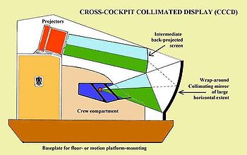
A breakthrough occurred in 1982 when the Rediffusion company of Crawley, UK, introduced their Wide-angle Infinity Display Equipment (WIDE(TM)) system. This used a curved mirror of large horizontal extent to allow distant-focus collimated viewing in a continuous, seamless, horizontal display, by pilots seated side-by-side. The Outside-World (OTW) image was back-projected on a screen above the replica cockpit, and it was the reflection from this screen that was viewed by the pilots. For a diagram of a cross-cockpit display and examples of flight simulators that use it, see the entry under Collimated light. To avoid the weight and fragility of using a large glass mirror, the reflective material was on a flexible mylar sheet. When the simulator is in operation, the flexible sheet is held to an accurate shape by being attached to a shaped former by suction pressure using a small pump. The other major flight simulation companies now produce their own types of mirror-based cross-cockpit displays and these are now utilized in most Full flight simulators of Regulatory Levels C and D. The original Cross-Cockpit display systems used three projectors mounted on top of the replica cockpit and had a Field-of-View (FoV) of 150 degrees horizontally by 30 degrees vertically. With five projectors the horizontal FoV could be extended to 220 degrees. Developments have allowed these figures for three- and five-projector systems to be extended to 180 degrees with three projectors and 240 degrees with five.

Types of flight training devices in service


Training for pilots

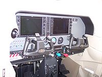
Cockpit of a twinjet flight simulator.
Flight simulation is used extensively in the aviation industry for the training of pilots and other flight crew in both civil and military aircraft. It is also used for the training of maintenance engineers in aircraft systems, and has applications in aircraft design and development, also in aviation and other research.
Several different types of devices are utilized in modern flight training. These range from simple Part-Task Trainers (PTTs) that cover one or more aircraft systems to Full Flight Simulators (FFS) with comprehensive aerodynamic and systems modeling. This spectrum encompasses a wide variety of fidelity in both physical cockpit characteristics and quality of software models, as well as various implementations of sensory cues such as sound, motion, and visual systems. The following training device types are in common use:
  • Cockpit Procedures Trainer (CPT) - Used to practice basic cockpit procedures, such as emergency checklists, and for cockpit familiarization. Certain aircraft systems may or may not be simulated. The aerodynamic model is usually extremely generic if one is even present at all. CPTs are usually not regulated.
  • Aviation Training Device (ATD) - Used for basic training of flight concepts and procedures. A generic flight model representing a "family" of aircraft is installed, and many common flight systems are simulated.
  • Basic Instrument Training Device (BITD) - A basic training device primarily focused on generic instrument flight procedures.
  • Flight and Navigation Procedures Trainer (FNPT) - Used for generic flight training. A generic, but comprehensive flight model is required, and many systems and environmental effects must be provided.
  • Flight Training Device (FTD) - Used for either generic or aircraft specific flight training. Comprehensive flight, systems, and environmental models are required. High level FTDs require visual systems but not the characteristics of a Full Flight Simulator (FFS), see below.
  • Full flight simulator (FFS) - Used for aircraft-specific flight training under rules of the appropriate National Civil Aviation Regulatory Authority. Under these rules, relevant aircraft systems must be fully simulated, and a comprehensive aerodynamic model is required. All FFS require outside-world (OTW) visual systems and a motion platform.
  • Full Mission Simulator (FMS) - used by the military to denote a simulator capable of training all aspects of an operational mission in the aircraft concerned.
In many professional flight schools, initial training is conducted partially in the aircraft, and partially in relatively low cost training devices such as FNPTs and FTDs. As the student becomes familiar with basic aircraft handling and flight skills, more emphasis is placed on instrument flying, cockpit resource management (CRM), and advanced aircraft systems, and the portion of flight training conducted in these devices increases significantly. Finally, for more advanced aircraft-specific training, Full Flight Simulators (FFS) are used, particularly as part of conversion to the Commercial Air Transport (CAT) aircraft that the pilot will eventually fly.
For many commercial pilots, most aircraft orientation and recurrent training is conducted in high level FTDs or FFS.
In comparison to training in an actual aircraft, simulation based training allows for the training of maneuvers or situations that may be impractical (or even dangerous) to perform in the aircraft, while keeping the pilot and instructor in a relatively low-risk environment on the ground. For example, electrical system failures, instrument failures, hydraulic system failures, environmental system failures, and even flight control failures can be simulated without risk to the pilots or an aircraft.
Instructors can also provide students with a higher concentration of training tasks in a given period of time than is usually possible in the aircraft. For example, conducting multiple instrument approaches in the actual aircraft may require significant time spent repositioning the aircraft, while in a simulation, as soon as one approach has been completed, the instructor can immediately preposition the simulated aircraft to an ideal (or less than ideal) location from which to begin the next approach.
Flight simulation also provides an economic advantage over training in an actual aircraft. Once fuel, maintenance, and insurance costs are taken into account, the operating costs of an FSTD are usually substantially lower than the operating costs of the simulated aircraft. For some large transport category airplanes, the operating costs may be several times lower for the FSTD than the actual aircraft.

Engineering simulation

Engineering flight simulators are used by aerospace manufacturers for such tasks as:
  • Development and testing of flight hardware. Simulation (emulation) and stimulation techniques can be used, the latter being where real hardware is fed artificially-generated or real signals (stimulated) in order to make it work. Such signals can be electrical, RF, sonar, etc., depending on the equipment to be tested.
  • Development and testing of flight software. It is much safer to develop critical flight software on simulators or using simulation techniques than it is to develop using actual aircraft in flight.
  • Development and testing of aircraft systems. For electrical, hydraulic, and flight control systems, full-size engineering rigs sometimes called 'Iron Birds' are used during the development of the aircraft and its systems.
     

Entertainment


Screenshot from FlightGear, a free and open source flight simulator
Amateur flight simulation refers to the simulation of various aspects of flight or the flight environment for purposes other than flight training or aircraft development. A large number of free or commercial flight simulators are available:
  • FlightGear, a free and open source flight simulator
  • X-Plane, also includes a Space Shuttle and Mars flight simulators
  • YS Flight Simulation 2000, a freeware flight simulator targeted at low end systems
  • Microsoft Flight Simulator Series - its latest installment (Microsoft Flight Simulator X) now includes space as an area to be discovered, with a payware space shuttle available.

    Technology


    Motion in flight simulators

    A Thales flight simulator at a pitch angle

    A Full flight simulator (FFS) duplicates relevant aspects of the aircraft and its environment, including motion. This is typically accomplished by placing a replica cockpit and visual system on a motion platform. A six degree-of-freedom (DOF) motion platform using six jacks is the modern standard, and is required for the so-called Level D flight simulator standard of civil aviation regulatory authorities such as FAA in the USA and EASA in Europe. Since the travel of the motion system is limited, a principle called 'acceleration onset cueing' (which see) is used. This simulates initial accelerations well, and then returns the motion system to a neutral position at a rate below the pilot's sensory threshold in order to prevent the motion system from reaching its limits of travel.
    Flight simulator motion platforms used to use hydraulic jacks but electric jacks are now being used. The latter do not need hydraulic motor rooms and other complications of hydraulic systems, and can be designed to give lower latencies (transport delays) compared to hydraulic systems. Level D flight simulators are used at training centers such as those provided by Airbus, FlightSafety International, CAE, Boeing Training and Flight Services (ex-Alteon) and at the training centers of the larger airlines. In the military, motion platforms are commonly used for large multi-engined aircraft and also in helicopters, except where a training device is designed for rapid deployment to another training base or to a combat zone.
    Statistically significant assessments of training transfer from simulator to the aircraft are difficult to make, particularly where motion cues are concerned. Large sample sizes of pilot opinion are required and many subjective opinions tend to be aired, particularly by pilots not used to making objective assessments and responding to a structured test schedule. However, it is generally agreed that a motion-based simulation gives the pilot closer fidelity of flight control operation and aircraft responses to control inputs and external forces. This is described as "handling fidelity", which can be assessed by test flight standards such as the numerical Cooper-Harper rating scale for handling qualities. Generally, motion-based aircraft simulation feels like being in an aircraft rather than in a static procedural trainer. In a re-structuring of civil flight training device characteristics and terminology that will take place in about 2012, the Level D Full flight simulator will be re-designated an ICAO Type 7 and will have improved specifications for both motion and visual systems. This is a result of a rationalisation of worldwide civil flight training devices through which 27 previous categories have been reduced to seven.

    Qualification and approval


    Procedure

    In order for a Flight Simulation Training Device (FSTD) to be used for flight crew training or checking, it must be evaluated by the local National Aviation Authority (NAA), such as the Federal Aviation Administration (FAA) in the United States. The training device in question is evaluated against a set of regulatory criteria, and a number of both objective and subjective tests are conducted on the device. The results of each test, along with other significant information about the FSTD and its operator, are recorded in a Qualification Test Guide (QTG).
    The result of the initial evaluation of the FSTD, called the Master QTG (MQTG), details the baseline performance of the device as accepted by the qualifying authority. A periodic re-evaluation, called a recurrent qualification, is performed regularly, generally in one year intervals (although the interval can be as low as six months for some FAA evaluations and as high as three years for some European evaluations), and the performance of the device is evaluated against the MQTG. Any significant deviations may result in the suspension or revocation of the device's qualification.
    The criteria against which an FSTD is evaluated are defined in one of a number of regulatory and/or advisory documents. In the United States and China, FSTD qualification is regulated in 14 CFR Part 60. In most of Europe, as well as several other parts of the world, the relevant regulations are defined in JAR-FSTD A and JAR-FSTD H. The testing requirements vary between the different levels of qualification, but almost all levels require that the FSTD show that it matches the flight characteristics of the aircraft or family of aircraft being simulated.
    The main exception to the above process is the evaluation of an ATD by the FAA. Rather than other FSTD, where each device is evaluated on an individual basis, ATDs are evaluated as a model line. When a manufacturer wishes to have a model of ATD approved, a document that contains the specifications of the model line and that proves compliance with the appropriate regulations is submitted to the FAA. If this document, called a Qualification Approval Guide (QAG) is approved, all future devices conforming to the QAG are automatically approved, and individual evaluation is neither required nor available.
    Until the publication of Part 60, qualification was called certification, and QTGs were called Approval Test Guides (ATGs). The terms certification and ATG no longer have any regulatory meaning other than for FSTD that remain qualified under FAA AC 120-45 or any other legacy standard.

    Flight Simulator "levels" and other categories

    The following levels of qualification are currently being granted for both airplane and helicopter FSTD:

    US Federal Aviation Administration (FAA)

    Flight Training Devices (FTD)
    • FAA FTD Level 4 - Similar to a Cockpit Procedures Trainer (CPT). This level does not require an aerodynamic model, but accurate systems modeling is required. Helicopter only.
    • FAA FTD Level 5 - Aerodynamic programming and systems modeling is required, but it may represent a family of aircraft rather than one specific model.
    • FAA FTD Level 6 - Aircraft model specific aerodynamic programming, control feel, and physical cockpit are required.
    • FAA FTD Level 7 - Model specific. All applicable aerodynamics, flight controls, and systems must be modeled. A vibration system must be supplied, and this is the first level to require a visual system. Helicopter only.
    Full Flight Simulators (FFS)
    • FAA FFS Level A - A motion system is required with at least three degrees of freedom. Airplane only.
    • FAA FFS Level B - Requires three axis motion and a higher-fidelity aerodynamic model than Level A. The lowest level of helicopter flight simulator.
    • FAA FFS Level C - Requires a motion platform with all six degrees of freedom. Also lower transport delay (latency) over levels A & B. The visual system must have an outside-world horizontal field of view of at least 75 degrees to each pilot.
    • FAA FFS Level D - The highest level of FFS qualification currently available. Requirements are for Level C with additions. The motion platform must have all six degrees of freedom, and the visual system must have an outside-world horizontal field of view of at least 150 degrees, with a Collimated (distant focus) display. Realistic sounds in the cockpit are required, also a number of special motion and visual effects.

    [European Aviation Safety Agency (EASA, ex JAA)

    Flight Navigation and Procedures Trainer (FNTP)
    • EASA FNPT Level I
    • EASA FNPT Level II
    • EASA FNTP Level III
    • MCC - Not a true "level" of qualification, but an add-on that allows any level of FNPT to be used for multi crew cooperation training.
    Flight Training Devices (FTD
    • EASA FTD Level 1
    • EASA FTD Level 2
    • EASA FTD Level 3 - Helicopter only.
    Full Flight Simulators (FFS)
    • EASA FFS Level A
    • EASA FFS Level B
    • EASA FFS Level C
    • EASA FFS Level D


    Credits

    The training or checking credits allowed of an FSTD are based on the level of qualification and the operator's training curriculum. For some experienced pilots, Level D FFS may be used for Zero Flight Time (ZFT) conversions from one type of aircraft to another. In ZFT conversions, no aircraft flight time is required, and the pilot first flies the aircraft (under the supervision of a Training Captain) on a revenue flight.

    Manufacturers

    Full Flight Simulator manufacturers include;
    • FlightSafety International (FSI) (United States),
    • Frasca International, Inc.
    • L-3 Link
    • Rockwell Collins
    • Opinicus
    • CAE Inc.
    • Mechtronix Systems (Canada)
    • Sim Industries in the Netherlands
    • Indra Sistemas in Spain
    • Indra Systems (United States)
    • Havelsan in Turkey
    • AXIS Flight Training Systems in Austria
    • Thales Group in France and the UK
    • CSTS Dinamika in Russia
    • Aerosim
    The UK Thales site at Crawley, near London Gatwick airport, is a successor to the ex-Rediffusion simulator factory. Another flight simulator manufacturer is Aerosim located in Burnsville, Minnesota, USA; their focus is making FTDs and VPTs (virtual procedure trainers).
    There are currently about 1280 Full Flight Simulators (FFS) in operation worldwide, certificated for pilot training in the Commercial Air Transport (CAT) sector by the relevant National Civil Aviation Regulatory Authorities (NAA, such as the FAA for the USA and EASA for Europe) , of which about 550 are in the USA, 75 in the UK, 60 in China (PRC), 50 each in Germany and Japan, and 40 in France. Of these, some 450 were made by CAE, mainly in their Montreal factory, about 380 by Thales and its predecessors Rediffusion, (Singer) Link-Miles, and Thomson CSF, and about 280 by Flight Safety International. L-3 Communications operates a facility in Arlington, Texas which manufactures flight simulators for the military; the division (Link Simulation and Training) traces its legacy back to Link's original invention.
    The TL39 3-DoF motion simulator with IOS at MAI University
    Flight simulators are also extensively used for research in various aerospace subjects, particularly in flight dynamics and man-machine interaction (MMI). Both regular and purpose-built research simulators are employed. They range from the simplest ones, which resemble video games, to very specific and extremely expensive designs such as LAMARS, installed at Wright-Patterson Air Force Base, Ohio. This was built by Northrop for the Air Force Research Laboratory (AFRL) and features a large scale five degrees of freedom motion system to a unique design and a 360 degree dome-mounted visual system. The most advanced research simulator with sustained G-capability, unlimited attitude control and a reconfigurable cockpit was developed in a joint-venture of TNO and AMST GmbH and is called DESDEMONA.

    Instructor operating stations

    Most simulators have Instructor Operating Stations (IOS). At the IOS, an instructor can quickly create any normal and abnormal condition in the simulated aircraft or in the simulated external environment. This can range from engine fires, malfunctioning landing gear, electrical faults, storms, downbursts, lightning, oncoming aircraft, slippery runways, navigational system failures and countless other problems which the crew need to be familiar with and act upon.
    Many simulators allow the instructor to control the simulator from the cockpit, either from a console behind the pilot's seats, or, in some simulators, from the co-pilot's seat on sorties where a co-pilot is not being trained. Some simulators are equipped with PDA-like devices in which the instructor can fly in the co-pilot seat and control the events of the simulation, while not interfering with the lesson.
    Flight simulators are an essential element in individual pilot as well as flight crew training. They save time, money and lives. The cost of operating even an expensive Level D Full Flight Simulator is many times less than if the training was to be on the aircraft itself and a cost ratio of some 1:40 has been reported for Level D simulator training compared to the cost of training in a real Boeing 747 aircraft.

    Modern high-end flight simulators


    Stewart platform
    High-end commercial and military flight simulators have large field-of-view (FoV) image generation and display systems of high resolution. All civil Full Flight Simulators (FFS) and many military simulators for large aircraft and helicopters also have motion platforms for cues of real motion. Platform motions complement the visual cues and are particularly important when visual cues are poor such as at night or in reduced visibility or, in cloud, non-existent. The majority of simulators with motion platforms use variants of the six cylinder Stewart platform to generate cues of initial acceleration. These platforms are also known as Hexapods (literally "six feet") and use an operating principle known as Acceleration onset cueing (which see). Motion bases using modern hexapod platforms can provide about +/- 35 degrees of the three rotations pitch, roll and yaw, and about one metre of the three linear movements heave, sway and surge.
    The NASA Ames Research Center in "Silicon Valley" south of San Francisco operates the Vertical Motion Simulator. This has a very large-throw motion system with 60 feet (+/- 30 ft) of vertical movement (heave). The heave system supports a horizontal beam on which are mounted rails of length 40 feet, allowing lateral movement of a simulator cab of +/- 20 feet. A conventional 6-degree of freedom hexapod platform is mounted on the 40 ft beam, and an interchangeable cabin is mounted on the hexapod platform. This design permits quick switching of different aircraft cabins. Simulations have ranged from blimps, commercial and military aircraft to the Space Shuttle. In the case of the Space Shuttle, the large Vertical Motion Simulator was used to investigate a longitudinal pilot-induced oscillation (PIO) that occurred on an early Shuttle flight just before landing. After identification of the problem on the VMS, it was used to try different longitudinal control algorithms and recommend the best for use in the Shuttle programme. After this exercise, no similar Shuttle PIO has occurred. The ability to simulate realistic motion cues was considered important in reproducing the PIO and attempts on a non-motion simulator were not successful (a similar pattern exists in simulating the roll-upset accidents to a number of early Boeing 737 aircraft, where a motion-based simulator is needed to replicate the conditions).
    AMST Systemtechnik (Austria) and TNO Human Factors (the Netherlands) have developed the Desdemona flight simulation system for the Netherlands-based research organisation TNO. This large scale simulator provides unlimited rotation via a gimballed cockpit. The gimbal sub-system is supported by a framework which adds vertical motion. Furthermore, this framework is mounted on a large rotating platform with an adjustable radius. The Desdemona simulator is designed to provide sustainable g-force simulation with unlimited rotational freedom.

    Radio-controlling simulators

    A specific field for flight simulation are radio-controlled models - mostly airplanes and helicopters - that are steered from the ground by a transmitter. Here a major part of the learning curve for the pilot is the coordination between finger movement - typically via two joysticks for pitch/yaw and nick/roll - and the model reaction. RC flight simulator software thus uses an input, mostly an USB cable, from the same transmitter that is used for the actual model. With this setup the pilot can learn basic flying procedures without the risk of damaging the model. Current products use photographic textures from real flight fields and mimic the model and weather behaviour with complex physical models.

    Advances in modern electronics

    Advances in electronics are now starting to bring pitch & roll motion platforms down into the realms of the high end home pilot. A simple combination of COTS (commercial off the shelf) hardware & software now allows home builders to construct simple pitch & roll platforms with some even building hexapod type platforms. These advances are also making it possible to home build controls with Force Feedback which simulates external forces on the control surfaces of the aircraft including hydraulic failures in control systems & the sensation of a landing on the controls. See also Force Feedback Australian flight & helisim builder Rainman Simulators currently has some of these systems in the development stage.