Πέμπτη 30 Ιουνίου 2011

Μουσείο Πολιτικής Αεροπορίας [GR]


Η 6η Απριλίου 1957 , είναι η ημέρα ίδρυσης της Ο.Α. ως Εθνικού Αερομεταφορέα, η οποια παρέλαβε από την μεταπολεμική Τ.Α.Ε Α.Ε και το Πολιτιστικό Κέντρο Εργαζομένων .Ο.Α. την έχει ανακηρύξει ως « Ημέρα Ολυμπιακής ». Την γενέθλεια αυτή ημέρα επέλεξε το Πολ.Κ.Ε.Ο.Α. και πραγματοποίησε εκδήλωση εγκαινίων ίδρυσης Μουσείου Πολιτικής Αεροπορίας, την Τετάρτη 06 Απρ 2011 στις 21 : 00, στις εγκαταστάσεις του, στο Πρώην Δυτικό Αεροδρόμιο Ελληνικού, με σκοπό την ευαισθητοποίηση της κοινής γνώμης στον παραπάνω στόχο.

Η άποψή μας:

Στην όμορφη αυτή εθνική προσπάθεια 
παρουσιάσθηκε, μέρος των εκθεμάτων που διαθέτει, τα οποια, στο σύνολο τους, προέρχονται από την πωληθείσα Ο.Α A.E. Για τον λόγο αυτόν δεν δύναται να χαρακτηρισθεί ως Μουσείο Πολιτικής Αεροπορίας, αλλά ως « Μουσείο Ελληνικού Εθνικού Αερομεταφορέως », χωρίς αυτό να σημαίνει ότι με την προσθήκη εκθεμάτων δεν δύναται να εξελιχθεί σε κάτι τέτοιο. Χαρακτηριστική και μοναδική η συλλογή διαφόρων στολών όλων των ειδικοτήτων, του εξομειωτού πτήσεων « FRASCA » καθώς και λοιπών συσκευών και μηχανημάτων τα οποια συνέθεταν τον ζωντανό οργανισμό της Ο.Α, εκτίθενται στον χώρο αυτό. Έγγραφα και βιβλία ωρών πτήσεων, με την πολλαπλή και άγνωστη συμμετοχή, της Ο.Α και των ανθρώπων της, στους διαφόρους εθνικούς αγώνες της Ελλάδος την περίοδο αυτή ( π.χ Τουρκική εισβολή στην Κύπρο το 1974 ) έρχονται να συμπληρώσουν την όλη εικόνα. Σημειώνεται ότι στην δύναμη του Πολ.Κ.Ε.Ο.Α ( Μουσείου ) ανήκουν και τα αεροπλάνα τύπου BOEING B - 727, B – 737 και B – 747 τα οποια ευρίσκονται σταθμευμένα στο δάπεδο σταθμεύσεως του, πρώην, ανατολικού αερολιμένος Ελληνικού, έχουν ανακαινισθεί μερικώς, πρόσφατα, ενώ έχει αιτηθεί και την διάθεση ενός ΝΙΧΟΝ YS-11 από την Π.Α το οποίο θα φέρει τα χρώματα της Ο.Α Α.Ε. και τα αντίστοιχα ελληνικά διακριτικά νηολογίου κλήσεως. Τέλος, αριθμός διαφόρων ειδικών οχημάτων ( από ποδηλάτου, περιόδου 1957, εως μεταφοράς εμπορευματοκιβωτίων και κλιμάκων ) καθώς και μια, ως εκ θαύματος διασωθείσα MERCEDES 250 automatic, του Ιδρυτή της Ο.Α Α.Ε αειμνήστου, Αριστοτέλους Ωνάση, συμπληρώνουν την αεροπορική αυτή συλλογή. Επίσης το Πολ.Κ.Ε.Ο.Α προχωρεί στην σύσταση, πλέον, ενός κοινωφελούς ιδρύματος, με την επωνυμία « ΜΟΥΣΕΙΟ ΠΟΛΙΤΙΚΗΣ ΑΕΡΟΠΟΡΙΑΣ », ενώ διεκδικεί ικανή έκταση εγκαταστάσεων στο ιστορικό, πρώην αεροδρόμιο του Ελληνικού, για την πραγματοποίηση του εθνικού αεροπορικού έργου του.

Σημαντικές ημερομηνίες:

Ο αγώνας του ΠΟΛ.Κ.Ε.Ο.Α. για την ίδρυση του Μουσείου Πολιτικής Αεροπορίας:
·   1995: Πρόταση Βάινσεχόφεν για αξιοποίηση του Ελληνικού
·   1997: Πρόταση ΠΟΛ.Κ.Ε.Ο.Α. για Μουσείο Πολιτικής Αεροπορίας
·   2000: Φάκελος του ΠΟΛ.Κ.Ε.Ο.Α. σε Κυβέρνηση – Κόμματα για δημιουργία Μουσείου Πολιτικής Αεροπορίας.
·   22 Μαρτίου 2001: Μετεγκατάσταση αεροδρομίου. Εντατικοποίηση των παρεμβάσεων για το όραμα της ίδρυσης Μουσείου.
·   2003: Τροποποίηση καταστατικού του ΠΟΛ.Κ.Ε.Ο.Α για δυνατότητα σύστασης νομικού προσώπου.
·   2003: Αγοράζουμε τα α/φη Β727, Β737, Β747
·   2003: ΝΑΙ του υπουργείου Μεταφορών στην πρότασή μας για ίδρυση Μουσείου.
·   2004: Ημερίδα του Τ.Ε.Ε. – Κατατίθεται στα πλαίσια της ημερίδας η πρότασή μας για την αναγκαιότητα ίδρυσης Μουσείου.
·   2004: Οργανισμός Ρυμθιστικού Σχεδίου Αθήνας: Θετική ανταπόκριση στην πρότασή μας για Μουσείο, στα πλαίσια του Μητροπολιτικού Πάρκου.
·   2004: Όμοφοι Δήμοι: Εντάσσουν στην πρότασή τους για το Μητροπολιτικό Πάρκο και την αναγκαιότητα για Μουσείο Πολιτικής Αεροπορίας και Αρχαιολογικό Μουσείο.
·   2007: Λεύκωμα «1957-2007: Μισός αιώνας στους ουρανούς». Για πρώτη φορά καταγράφεται  η ιστορία της Ο.Α., με αφορμή τα 50 της χρόνια.
·   2008: Συμμετοχή στη δημόσια διαβούλευση του ΥΠΕΧΩΔΕ, κατάθεση πρότασης του ΠΟΛ.Κ.Ε.Ο.Α. για Μουσείο Πολιτικής Αεροπορίας, στα πλαίσια του Μητροπολιτικού Πάρκου.
·   2009: Ενδιαφέρον της Boeing
·   2009: Κατάθεση δικαιολογητικών σύμφωνα με το νόμο στο υπ. Οικονομίας και Οικονομικών, για τη σύσταση Κοινωφελούς Ιδρύματος Ιδιωτικού Δικαίου με την επωνυμία «Μουσείο Πολιτικής Αεροπορίας».
·   2010: Ενημέρωση της νέας Κυβέρνησης και του πρωθυπουργού, σχετικά με την πρόταση ΠΟΛ.Κ.Ε.Ο.Α. για Μουσείο, στα πλαίσια του Μητροπολιτικού Πάρκου.
·   2010: Προτάσεις Φορέων, Δήμων, επίκουρου καθ/τη του Ε.Μ.Π. κ.Νίκου Μπελαβίλα, ΟΡΣΑ, απαντά θετικά για το Μουσείο στο Ελληνικό.
·   6 Απριλίου 2011: «Ένα Νέο Μουσείου Γεννιέται» στο Ελληνικό.
·   17 Μαίου 2011: Εκδήλωση «Μητροπολιτικό Πάρκο Ελληνικού», της σχολής Αρχιτεκτόνων του Εθνικού Μετσόβιου Πολυτεχνείου.

Στόχος του Κοινωφελούς Ιδρύματος είναι να καταγράφει και να παρουσιάζει την εξέλιξη της Πολιτικής Αεροπορίας και την ιστορική διαδρομή των αερομεταφορών στη χώρα μας.


Είναι χρέος μας, ως άνθρωποι που μετείχαμε σε αυτήν τη διαδικασία, να παραδώσουμε τις αναμνήσεις μας στις επόμενες γενιές.


Καλούμε εσάς, τα μέλη μας και τους φίλους της Αεροπορίας, να βοηθήσετε για να προχωρήσουμε.
Επίσης, καλούμε τον κόσμο και τα μέλη μας, που διατηρούν αντικείμενα στην κατοχή τους, να τα φέρουν ώστε να συμπεριληφθούν - εκτεθούν στο υπό σύσταση Μουσείο Πολιτικής Αεροπορίας.

Ιστορία του χώρου:

Το κτίριο των υπερπόντιων πτήσεων στο πρώην Δυτικό Α/Σ Ελληνικού – Πολυχώρος ΠΟΛ.Κ.Ε.Ο.Α. που φιλοξενεί το Μουσείο Πολιτικής Αεροπορίας έχει την κάτωθι ιστορία:
Το κτίριο ενταγμένο στα έργα ανάπλασης του αεροδρομίου Ελληνικού, μελετήθηκε αρχικά το 1974 για να στεγάσει τις Υπηρεσίες Αναχωρήσεων Επιβατών Εξωτερικού, πέραν των πτήσεων προς την Ευρώπη, όταν η Ο.Α. εξυπηρετούσε επιβάτες που ταξίδευαν και στις πέντε ηπείρους.
Το 1978, μελετήθηκε εκ νέου η στατική επάρκεια (αντοχή σε πρόσθετα φορτία) του κτιρίου, ώστε το 1979, με τη σχετικές ενισχύσεις, να στεγάσει τα μηχανήματα Ηλεκτρονικών Υπολογιστών της Ο.Α. που καθιστούσαν πλέον αποτελεσματικές τις Κρατήσεις Θέσεων και τις Οικονομικές Υπηρεσίες.
Το κτίριο αυτό, με τα ίδια μορφολογικά στοιχεία, παραμένει μέχρι σήμερα σε λειτουργία.
Το 1980, το Δ/Σ της Ο.Α., αποφασίζει την κατασκευή του νέου ολοκληρωμένου κτιρίου Ηλεκτρονικού Υπολογιστή σε ιδιωτικό οικόπεδο κοντά στο Ανατολικό Αεροδρόμιο.
Στο τελευταίο αυτό κτίριο, συνέχισε να χτυπάει η καρδιά της Ο.Α. και μετά την μεταφορά των Υπηρεσιών της στο Δ.Α.Α. στα Σπάτα.
Εν τω μεταξύ στο κτίριο Υπερπόντιων Πτήσεων με το ΠΟΛ.Κ.Ε.Ο.Α. κραιτιέται ζωντανή η μνήμη μιας Εταιρείας Ονειρικών Ταξιδιών, στις πέντε ηπείρους, που έζησε πάνω από 50 χρόνια στις καρδιές των Ελλήνων…

 Τέλος θα θέλαμε να ευχαριστήσουμε τον κύριο Βασίλη Τσατσαράγκο για τις πληροφορίες και τις εικόνες που μας απέστειλε.

Πληροφορίες για επίσκεψη ο κάθε ενδιαφερόμενος μπορεί να λάβει στα:
Τηλέφωνα : 210 3563357 – 210 3563938
e-mail: polkeoa@otenet.gr
Πρώην Δυτικό Αεροδρόμιο Ελληνικού 167 77 – ΕΛΛΗΝΙΚΟ

Δευτέρα 27 Ιουνίου 2011

Boeing 787 [EN]

The Boeing 787 Dreamliner is a long-range, mid-size wide-body, twin-engine jet airliner developed by Boeing Commercial Airplanes. It seats 210 to 330 passengers, depending on the variant. Boeing states that it is the company's most fuel-efficient airliner and the world's first major airliner to use composite materials for most of its construction. The 787 consumes 20% less fuel than the similarly-sized Boeing 767. Some of its distinguishing features include a four-panel windshield, noise-reducing chevrons on its engine nacelles, and a smoother nose contour.
The aircraft's initial designation was 7E7, prior to its renaming in January 2005. The first 787 was unveiled in a roll-out ceremony on July 8, 2007, at Boeing's Everett assembly factory, by which time it had become the fastest-selling wide-body airliner in history with 677 orders. By March 2011, 835 Boeing 787s had been ordered by 56 customers. As of 2011, launch customer All Nippon Airways has the largest number of 787s on order.
The 787 development and production has involved a large-scale collaboration with numerous suppliers around the globe. It is being assembled at the Boeing Everett Factory in Everett, Washington. Aircraft will also be assembled at a new factory in North Charleston, South Carolina. Both sites will deliver 787s to airline customers. Originally planned to enter service in May 2008, the project has suffered from repeated delays and is now more than three years behind schedule. The airliner's maiden flight took place on December 15, 2009, and it is currently undergoing flight testing with a goal of receiving certification in mid-2011 and entering service with All Nippon Airways in the third quarter of 2011.


Development


Background

During the late 1990s, Boeing began considering replacement aircraft programs as sales for the 767 and Boeing 747-400 slowed. The company proposed two new aircraft, the 747X, which would have lengthened the 747-400 and improved efficiency, and the Sonic Cruiser, which would have achieved 15% higher speeds (approximately Mach 0.98) while burning fuel at the same rate as the existing 767. Market interest for the 747X was tepid, but the Sonic Cruiser had brighter prospects. Several major airlines in the United States, including Continental Airlines, initially showed enthusiasm for the Sonic Cruiser concept, although they also expressed concerns about the operating cost.
Early impression of the 7E7 in blue and white livery
Earlier proposed design configuration of the Boeing 7E7.
The global airline market was upended by the September 11, 2001 attacks and increased petroleum prices, making airlines more interested in efficiency than speed. The worst-affected airlines, those in the United States, had been considered the most likely customers of the Sonic Cruiser, and thus Boeing officially canceled the Sonic Cruiser on December 20, 2002. Switching tracks, the company announced an alternative product using Sonic Cruiser technology in a more conventional configuration, the 7E7, on January 29, 2003. The emphasis on a smaller midsize twinjet rather than a large 747-size aircraft represented a shift from hub-and-spoke theory towards the point-to-point theory, in response to analysis of focus groups.
The 7E7 looks fairly traditional on the outside, but it will be dramatically different on the inside.
Times
The replacement for the Sonic Cruiser project was dubbed the "7E7" (with a development code name of "Y2"). Technology from the Sonic Cruiser and 7E7 was to be used as part of Boeing's project to replace its entire airliner product line, an endeavor called the Yellowstone Project (of which the 7E7 became the first stage). Early concept images of the 7E7 included rakish cockpit windows, a dropped nose and a distinctive "shark-fin" tail. The "E" was said to stand for various things, such as "efficiency" or "environmentally friendly"; however, in the end, Boeing claimed that it stood merely for "Eight". In July 2003, a public naming competition was held for the 7E7, for which out of 500,000 votes cast online the winning title was Dreamliner. Other names in the pool included eLiner, Global Cruiser and Stratoclimber.

Design effort

On April 26, 2004, Japanese airline All Nippon Airways became the launch customer for the 7E7 Dreamliner, by announcing a firm order for 50 aircraft with deliveries to begin in late 2008. All Nippon Airways's order was initially specified as 30 787-3, 290–330 seat, one-class domestic aircraft, and 20 787-8, long-haul, 210–250 seat, two-class aircraft for regional international routes such as Tokyo Narita–Beijing. The aircraft would allow All Nippon Airways to open new routes to cities not previously served, such as Denver, Moscow, and New Delhi. The 787-3 and 787-8 were to be the initial variants, with the 787-9 entering service in 2010.
B787 in launch customer All Nippon Airways' blue and white livery. In the background are two assembly halls, with huge doors facing left. Vehicles are parked in front of the halls.
All Nippon Airways launched the 787 Dreamliner program with an order for 50 aircraft in 2004. This aircraft made an emergency landing during a test flight in Texas, on November 9, 2010.

The 787 was designed to become the first production composite airliner, with the fuselage assembled in one-piece composite barrel sections instead of the multiple aluminum sheets and some 50,000 fasteners used on existing aircraft. Boeing selected two new engine types to power the 787, the General Electric GEnx and Rolls-Royce Trent 1000. Boeing claimed the 787 would be near to 20% more fuel-efficient than the 767, with one-third of the efficiency gain from the engines, another third from aerodynamic improvements and the increased use of lighter-weight composite materials, and the final third from advanced systems.
During the design phase, the 787 underwent extensive wind tunnel testing at Boeing's Transonic Wind Tunnel, QinetiQ's five-meter wind tunnel at Farnborough, UK, and NASA Ames Research Center's wind tunnel, as well as at the French aerodynamics research agency, ONERA. The final styling of the aircraft was more conservative than earlier proposals, with the fin, nose, and cockpit windows changed to a more conventional form. By the end of 2004, customer-announced orders and commitments for the 787 reached 237 aircraft. Boeing initially priced the 787-8 variant at US$120 million, a low figure that surprised the industry. In 2007, the list price was US$146–151.5 million for the 787-3, US$157–167 million for the 787-8 and US$189–200 million for the 787-9.


Manufacturing and suppliers

After stiff competition, Boeing announced on December 16, 2003, that the 787 would be assembled in its factory in Everett, Washington. Instead of building the complete aircraft from the ground up in the traditional manner, final assembly would employ just 800 to 1,200 people to join completed subassemblies and to integrate systems. Boeing assigned its global subcontractors to do more assembly themselves and deliver completed subassemblies to Boeing for final assembly. This approach was intended to result in a leaner and simpler assembly line and lower inventory, with pre-installed systems reducing final assembly time by three-quarters to three days.

Assembly of Section 41 of a Boeing 787
Subcontracted assemblies included wing manufacture (Mitsubishi Heavy Industries, Japan, central wing box) horizontal stabilizers (Alenia Aeronautica, Italy; Korea Aerospace Industries, South Korea); fuselage sections (Global Aeronautica, Italy; Boeing, North Charleston, USA; Kawasaki Heavy Industries, Japan; Spirit AeroSystems, Wichita, USA; Korean Air, South Korea); passenger doors (Latécoère, France); cargo doors, access doors, and crew escape door (Saab, Sweden); floor beams (TAL Manufacturing Solutions Limited, India); wiring (Labinal, France); wing-tips, flap support fairings, wheel well bulkhead, and longerons (Korean Air, South Korea); landing gear (Messier-Dowty, France); and power distribution and management systems, air conditioning packs (Hamilton Sundstrand, Connecticut, USA). Boeing is considering bringing construction of the 787-9 tail in house; the tail of the 787-8 is currently made by Alenia.
To speed delivery of the 787's major components, Boeing modified several used 747-400s into 747 Dreamlifters to transport 787 wings, fuselage sections, and other smaller parts. Japanese industrial participation was very important to the project, with a 35% work share, the first time Japanese firms had taken a lead role in mass production of Boeing airliner wings, and many of the subcontractors supported and funded by the Japanese government. On April 26, 2006, Japanese manufacturer Toray Industries and Boeing announced a production agreement involving US$6 billion worth of carbon fiber, extending a 2004 contract and aimed at easing production concerns.

Production and delivery delays

Boeing had originally planned for a first flight by the end of August 2007 and premiered the first 787 at a rollout ceremony on July 8, 2007, which matches the aircraft's designation in the US-style month-day-year format (7/8/07). However, the aircraft's major systems had not been installed at that time, and many parts were attached with temporary non-aerospace fasteners requiring their later replacement with flight fasteners. Although intended to shorten the production process, 787 subcontractors initially had difficulty completing the extra work, because they could not procure the needed parts, perform the subassembly on schedule, or both, leaving remaining assembly work for Boeing to complete as "traveled work".
The Everett Factory Hall's huge door opens as the first 787 is rolled out. Surrounded the aircraft are guests and the public.
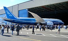
The 787 Dreamliner's first public appearance was webcast live on July 8, 2007.
On September 5, Boeing announced a three-month delay, blaming a shortage of fasteners as well as incomplete software. On October 10, 2007, a second three-month delay to the first flight and a six-month delay to first deliveries was announced due to problems with the foreign and domestic supply chain, including an ongoing fastener shortage, the lack of documentation from overseas suppliers, and continuing delays with the flight guidance software. Less than a week later, Mike Bair, the 787 program manager was replaced. On January 16, 2008, Boeing announced a third three-month delay to the first flight of the 787, citing insufficient progress on "traveled work". On March 28, 2008, in an effort to gain more control over the supply chain, Boeing announced that it planned to buy Vought Aircraft Industries' interest in Global Aeronautica; the company later agreed to also purchase Vought's North Charleston, S.C. factory.
On April 9, 2008, Boeing officially announced a fourth delay, shifting the maiden flight to the fourth quarter of 2008, and delaying initial deliveries by around 15 months to the third quarter of 2009. The 787-9 variant was postponed to 2012 and the 787-3 variant was to follow with no firm delivery date. On November 4, 2008, the company announced a fifth delay due to incorrect fastener installation and the Boeing machinists strike, stating that the first test flight would not occur in the fourth quarter of 2008. fter assessing the 787 program schedule with its suppliers, Boeing confirmed on December 11, 2008 that the first flight would be delayed until the second quarter of 2009.
On June 15, 2009, during the Paris Air Show, Boeing said that the 787 would make its first flight within two weeks. However, on June 23, 2009, Boeing announced that the first flight is postponed "due to a need to reinforce an area within the side-of-body section of the aircraft". Boeing provided an updated 787 schedule on August 27, 2009, with the first flight planned to occur by the end of 2009 and deliveries to begin at the end of 2010. The company expects to write off US$2.5 billion because it considers the first three Dreamliners built unsellable and suitable only for flight tests.
Boeing announced on July 15, 2010, that the first delivery to launch customer All Nippon Airways could slip into 2011, and on August 27, 2010 it confirmed that the first delivery would be delayed until early 2011. Boeing and Rolls-Royce state a lack of Trent 1000 engines as the cause, following shutdown of Rolls-Royce's test facility after a blowout in a Trent 1000 during ground testing on August 2. In August 2010, it was announced that Boeing was facing a US$1 billion compensation claim from Air India due to the delays for the 27 Dreamliners it has on order. Within months, in early November 2010, it was reported that some early 787 deliveries may be delayed, in one case some three months, to allow for rework to address issues found during flight testing. In January 2011, Boeing announced that the first 787 delivery was rescheduled to the third quarter of 2011 due to software and electrical updates following the in-flight fire in November 2010.
On April 20, 2011 the National Labor Relations Board found that Boeing's second production line for the 787 in South Carolina violated two sections of the National Labor Relations Act.

Pre-flight ground testing


The first Boeing 787 underwent taxi tests at Paine Field in November and December 2009.
As Boeing worked with its suppliers on early 787 production, the aircraft design had proceeded through a series of test goals. On August 7, 2007, on-time certification of the Rolls-Royce Trent 1000 engine by European and US regulators was received. On August 23, 2007, a crash test involving a vertical drop of a partial composite fuselage section from about 15 ft (4.6 m) onto a 1 in (25 mm)-thick steel plate occurred in Mesa, Arizona; the results matched what Boeing's engineers had predicted, allowing modeling of various crash scenarios using computational analysis instead of further physical tests.
The alternative GE GEnx-1B engine achieved certification on March 31, 2008. On June 20, 2008, the 787 team achieved "Power On" of the first aircraft, powering and testing the aircraft's electrical supply and distribution systems. A non-flight 787 test airframe was built for static testing, and on September 27, 2008, over a period of nearly two hours, the fuselage was successfully tested at 14.9 psi (102.7 kPa), which is 150 percent of the maximum pressure expected in commercial service (i.e., when flying at maximum cruising altitude). In December 2008, the Federal Aviation Administration (FAA) passed the maintenance program for the 787.
On May 3, 2009, the first test 787 was moved to the flight line following extensive factory-testing, including landing gear swings, systems integration verification, and a total run-through of the first flight. Boeing spent most of May 2009 conducting tests on the first 787 in preparation for first flight planned for July 2009. But the late discovery of a structural issue concerning the wing-to-body ("side-of-body") joint delayed first flight until December 2009. On March 28, 2010, the 787 completed the ultimate wing load test, which requires that the wings of a fully assembled aircraft be loaded to 150% of design limit load and held for 3 seconds. The wings were flexed approximately 25 ft (7.6 m) upward during the test. Unlike past aircraft however, the wings were not tested to failure. On April 7, Boeing announced that analysis of the data showed the test was a success. On December 12, 2009, the first 787 completed high speed taxi tests, the last major step before flight.

Takeoff of the first Boeing 787 built on its maiden flight

Flight test program

On December 15, 2009, Boeing conducted the Dreamliner's maiden flight with the first 787-8, originating from Snohomish County Airport in Everett, Washington at 10:27 am PST, and landing at Boeing Field in King County, Washington at 1:35 pm PST. Originally scheduled for four hours, the test flight was shortened to three hours because of bad weather. Boeing's schedule called for a 9-month flight test campaign (later revised to 8.5 months). The company's previous major aircraft, the 777, took 11 months with nine aircraft, partly to demonstrate 180-min ETOPS, one of its main features.
The 787 flight test program is composed of 6 aircraft, ZA001 through ZA006, four with Rolls-Royce Trent 1000 engines and two with GE GEnx-1B64 engines. The second 787, ZA002 in All Nippon Airways livery, flew to Boeing Field on December 22, 2009 to join the flight test program; the third 787, ZA004 joined the test fleet with its first flight on February 24, 2010, followed by ZA003 on March 14, 2010. On March 24, 2010, testing for flutter and ground effects was completed, clearing the aircraft to fly its entire flight envelope.
Front/side view of white 787 on static display. Stairway is positioned ahead of the right engine for access into cabin.
The first 787 to visit Europe, ZA003 on display at the 2010 Farnborough Airshow
On April 23, 2010 Boeing delivered their latest 787 to a hangar at Eglin Air Force Base, Florida for extreme weather testing in temperatures ranging from 115 °F (46 °C) to −45 °F (46 °C to −42 °C), with all steps necessary to prepare for takeoff taken once the plane stabilizes at either temperature extreme. Dreamliner ZA005, the fifth 787 and the first with General Electric GEnx engines began ground engine tests in May 2010. ZA005 made its first flight on June 16, 2010 and joined the flight test program. In June 2010, gaps were discovered in the horizontal stabilizers of test aircraft, due to improperly installed shims; all aircraft produced then were to be inspected and repaired. The 787 made its first appearance at an international air show at the Farnborough Airshow, UK on July 18, 2010.
In September 2010, it was reported that a further two 787s might join the test fleet, making a total of eight flight test aircraft. On September 10, 2010, a partial engine surge or runaway occurred in a Trent engine on ZA001 at Roswell. On October 4, 2010, the sixth 787, ZA006 joined the test program with its first flight.
On November 9, 2010, Boeing 787, ZA002 made an emergency landing after smoke and flames were detected in the main cabin during a test flight over Texas. A Boeing spokeswoman said the airliner landed safely and the crew was evacuated after landing at the Laredo International Airport, Texas. The electrical fire caused some systems to fail before landing. Following this incident, Boeing suspended flight testing on November 10, 2010. Ground testing was performed instead. On November 22, 2010, Boeing announced that the in-flight fire can be primarily attributed to foreign object debris (FOD) that was present in the electrical bay. After electrical system and software changes, the 787 resumed company flight testing on December 23, 2010.
Certification by the European Aviation Safety Agency is expected by the end of 2011. On February 24, 2011, Boeing announced that the 787 had completed 80% of the test conditions for Rolls-Royce Trent 1000 engine and 60% of the conditions for the General Electric GEnx-1B engine. As of June 17, 2011, the seven 787 test aircraft have flown 3,989 hours in 1,461 flights combined.

Design

The longest-range 787 variant can fly 8,000 to 8,500 nautical miles (14,800 to 15,700 km), enough to cover the Los Angeles to Bangkok or New York City to Taipei routes. It will have a cruising airspeed of Mach 0.85 (561 mph, 903 km/h at typical cruise altitudes). The 787-8 and −9 will be certified to 330 minute ETOPS capability. External features include raked wingtips and engine nacelles with noise-reducing serrated edges. The two different engine models compatible with the 787 use a standard electrical interface to allow an aircraft to be fitted with either Rolls-Royce or General Electric engines. This aims to save time and cost when changing engine types; while previous aircraft can have engines changed to those of a different manufacturer, the high cost and time required makes it rare. In 2006, Boeing addressed reports of an extended change period by stating that the 787 engine swap was intended to take 24 hours; engine interchangeability, it is reported, makes the 787 a more flexible asset to airlines, allowing them to change easily from one manufacturer's engine to the other if required.

Airframe

Diagrams of outlines of three different aircraft imposed over one another.
Size comparison of the Boeing 787–8 (black outline) with the Boeing 777–300 (pink), 767-300 (cyan), and 737–800 (green).
The 787 features lighter-weight construction. Its materials, listed by weight, are 50% composite, 20% aluminum, 15% titanium, 10% steel, and 5% other; the aircraft will be 80% composite by volume. Each 787 contains approximately 35 short tons of carbon fiber reinforced plastic (CFRP), made with 23 tons of carbon fiber. Aluminum is used on wing and tail leading edges, titanium used mainly on engines and fasteners, with steel used in various places.
Carbon fiber composites have a higher strength-to-weight ratio than traditional aircraft materials, and help make the 787 a lighter aircraft. Composites are used on fuselage, wings, tail, doors, and interior. Boeing had built and tested the first commercial aircraft composite section while examining the Sonic Cruiser concept nearly five years before; the Bell Boeing V-22 Osprey military transport uses over 50% composites, and the C-17 has over 16,000 lb (7,300 kg) of structural composites.
In 2006, Boeing launched the 787 GoldCare program. This is an optional, comprehensive life-cycle management service whereby aircraft in the program are routinely monitored and repaired as needed. This is the first program of its kind from Boeing: Post-sale protection programs are not new, but have usually been offered by third party service centers. Boeing is also designing and testing composite hardware so inspections are mainly visual. This will reduce the need for ultrasonic and other non-visual inspection methods, saving time and money.

Boeing 787 flight deck


Flight systems

On the 787, Honeywell and Rockwell-Collins provide flight control, guidance, and other avionics systems, including standard dual head up guidance systems, while Thales supplies the integrated standby flight display and electrical power conversion system. A version of Ethernet (Avionics Full-Duplex Switched Ethernet (AFDX) / ARINC 664) will be used to transmit data between the flight deck and aircraft systems. The flight deck features LCD multi-function displays, all of which will use an industry standard GUI widget toolkit (Cockpit Display System Interfaces to User Systems / ARINC 661). The Lockheed Martin Orion spacecraft will use a glass cockpit derived from Honeywell International's 787 flight deck. The 787 flight deck includes two head-up displays (HUDs) as a standard feature.Like other Boeing airliners, the 787 will use a yoke instead of a side-stick. The future integration of forward looking infrared into the HUD system for thermal sensing so the pilots can "see" through the clouds is under consideration.

Angled planform view of the second 787 Dreamliner during flight testing
The most notable contribution to efficiency is the new electrical architecture, which replaces bleed air and hydraulic power sources with electrically powered compressors and pumps, as well as completely eliminating pneumatics and hydraulics from some subsystems (e.g., engine starters or brakes). The 787's engines use all-electrical bleedless systems, eliminating the superheated air conduits normally used for aircraft power, de-icing, and other functions. Another new system is a wing ice protection system that uses electro-thermal heater mats on the wing slats instead of hot bleed air that has been traditionally used.
An active gust alleviation system, similar to the system used on the B-2 bomber, improves ride quality during turbulence. Boeing, as part of its "Quiet Technology Demonstrator 2" project, is experimenting with several engine noise-reducing technologies for the 787. Among these are a redesigned air inlet containing sound-absorbing materials and redesigned exhaust duct covers whose rims are tipped in a toothed pattern to allow for quieter mixing of exhaust and outside air. Boeing expects these developments to make the 787 significantly quieter both inside and out.

Interior

The 787-8 is designed to seat 234 passengers in a three-class setup, 240 in two-class domestic configuration, and 296 passengers in a high-density economy arrangement. Seat rows can be arranged in four to six abreast in first or business (e.g., 1–2–1, 2–2–2), with eight or nine abreast in economy (e.g., 3–2–3, 2–4–2, 3–3–3). Typical seat room ranges from 46 to 61 in (120 to 150 cm) pitch in first, 36 to 39 in (91 to 99 cm) in business, and 32 to 34 in (81 to 86 cm) in economy.
787 mock-up. It demonstrates the 787's spacious cabin. Above the brown seats are overhead bins.
Mockup of early Dreamliner cabin concept
Cabin interior width is approximately 18 feet (547 cm) at armrest, 1 inch (2.5 cm) over what was originally planned, and 15 in (38 cm) greater than that of the Airbus A330 and A340, while 5 in (13 cm) less than the A350 and 16 in (41 cm) less than the 777. For economy class in 3–2–3 or 2–4–2 arrangements, seat-bottom widths will be 18.5 in (47 cm), comparable to that found on the Boeing 777, and recommended by detailed passenger ergonomics studies; for 3–3–3 and the 2–5–2 maximum passenger density layout, seat widths would be 17.18 in (43.55 cm), with most airlines expected to select the 3–3–3 maximum passenger density configuration. Boeing engineers designed the 787 interior to better accommodate persons with mobility, sensory, and cognitive disabilities. For example, a 56-inch (142 cm) by 57-inch (145 cm) convertible lavatory includes a movable center wall that allows two separate lavatories to become one large, wheelchair-accessible facility.

Interior mockup photo showing windows and LED mood lighting options for the 787 Dreamliner.
The 787's cabin windows are larger in area than all other civil air transports in-service or in development, with dimensions of 10.7 by 18.4 in (27 by 47 cm), and a higher eye level so passengers can maintain a view of the horizon. Electrochromism-based "auto-dimming" (smart glass) instead of window shades reduces cabin glare while maintaining transparency. These are to be supplied by PPG Industries. Standard for the first time on a jetliner, cabin lighting uses light-emitting diode (LED) in three colors instead of fluorescent tubes, allowing the aircraft to be entirely 'bulbless' and have 128 color combinations.
The internal pressure will be increased to the equivalent of 6,000 feet (1,800 m) altitude instead of the 8,000 feet (2,400 m) on conventional aircraft. According to Boeing, in a joint study with Oklahoma State University, this will significantly improve passenger comfort. A higher cabin pressure is possible in part because of better properties of composite materials. Higher humidity in the passenger cabin is possible because of the use of composites, which do not corrode. Cabin air is provided by electrically driven compressors using no engine-bleed air. An advanced cabin air-conditioning system provides better air quality: Ozone is removed from outside air; HEPA filters remove bacteria, viruses, and fungi; and a gaseous filtration system removes odors, irritants, and gaseous contaminants.

Technical concerns

Composites


Disassembled composite fuselage section of the Boeing 787
The risks of using a composite fuselage have been questioned by a former Boeing engineer, noting that carbon fiber, unlike metal, does not visibly show cracks and fatigue; the rival A350 was later announced to be using composite panels on a frame, a more traditional approach, which its contractors regarded as less risky. Further concerns include that, during crash-landings, survivable in metal planes, a composite fuselage could shatter and burn with toxic fumes. The porous properties of composite materials, allowing them to absorb unwanted moisture, have been questioned. As the aircraft reaches altitude, the moisture expands, and may cause delamination of the composite materials, and structural weakness over time. Boeing has dismissed criticisms of its fuselage materials, insisting that composites have been used on wings and other passenger aircraft parts for many years, and they have not been an issue. They have also stated that special defect detection procedures will be put in place to detect any potential hidden damage. Another concern arises from the risk of lightning strikes, with composite having as much as 1,000 times less electrical conductivity than aluminum, increasing the risk of damage. Boeing has stated that the 787's lightning protection will meet FAA requirements, and FAA management was planning to adjust some requirements, which will help the 787 show compliance. In summer 2010, a 787 experienced an in-flight lightning strike without damage.

Weight issues

While Boeing had been working to trim excess weight since assembly of the first airframe began, common for new aircraft in development, the company has stated that the first six 787s will be overweight, with the first aircraft expected to be 5,000 lb (2,270 kg) heavier than specified. The seventh and subsequent aircraft will be the first optimized 787s and are expected to meet all goals, with Boeing working on weight reductions. Boeing has redesigned some parts and made more use of titanium. According to International Lease Finance Corporation's (ILFC) Steven Udvar-Hazy, the 787-9's operating empty weight is around 14,000 lb (6,350 kg) overweight, which also could be a problem for the proposed 787-10.
In May 2009, a press report indicated a 10–15% range reduction, about 6,900 nmi (12,800 km) instead of the originally promised 7,700 to 8,200 nmi (14,800–15,700 km), for early aircraft that were about 8% overweight. Substantial redesign work is expected to correct this, which will complicate increases in production rates; Boeing stated the early 787-8s will have a range of almost 8,000 nmi (14,800 km). There have also been reports that this led Delta to delay deliveries of 787s it inherited from Northwest in order to take later planes that may be closer to the original estimates. Other airlines are suspected to have been given discounts to take the earlier models. Shanghai Airlines stated in March 2009 it wished to either delay or cancel its first order. Boeing expects to have the weight issues addressed by the 21st production model.

Computer networks

In January 2008, previous FAA concerns came to light regarding protection of the 787's computer networks from possible intentional or unintentional passenger access. The computer network in the passenger compartment, designed to give passengers in-flight internet access, is connected to the airplane's control, navigation, and communication systems. Boeing called the report "misleading", saying that various hardware and software solutions are employed to protect the airplane systems, including air gaps for the physical separation of the networks, and firewalls for their software separation. Measures are provided so data cannot be transferred from the passenger internet system to the maintenance or navigation systems. As part of certification, Boeing plans to demonstrate to the FAA that these provisions are acceptable.

Variants


The Boeing 787–8, the first model of the aircraft under production
Boeing has offered three variants of the 787 from the program launch in 2004. The 787-8 is scheduled to enter service in 2011; the 787-9 is to enter service in 2013.

787-8

The 787-8 is the base model of the 787 family, with a length of 186 feet (57 m) and a wingspan of 197 feet (60 m) and a range of 7,650 to 8,200 nautical miles (14,200 to 15,200 km), depending on seating configuration. The 787-8 seats 210 passengers in a three-class configuration. The variant will be the first of the 787 line to enter service in 2011. Boeing is targeting the 787-8 to replace the 767-200ER and 767-300ER, as well as expand into new non-stop markets where larger planes would not be economically viable. The bulk of 787 orders are for the 787-8.

787-9

The 787-9 will be the first variant of the 787 with a "stretched" or lengthened fuselage, seating 250–290 in three classes with a range of 8,000 to 8,500 nautical miles (14,800 to 15,750 km). This variant differs from the 787-8 in several ways, including structural strengthening, a lengthened fuselage, a higher fuel capacity, a higher maximum take-off weight (MTOW), but with the same wingspan as the 787-8. The targeted date for entry into service (EIS), originally planned for 2010, was scheduled for early 2013 in December 2008. Boeing is targeting the 787-9 to compete with both passenger variants of the Airbus A330 and to replace their own 767-400ER. Like the 787-8, it will also open up new non-stop routes, flying more cargo and fewer passengers more efficiently than the 777-200ER or A340-300/500. The firm configuration was finalized on July 1, 2010.

Artist's impression of the stretched 787-9, designed with greater range and payload capability
When first launched, the 787-9 had the same fuel capacity as the other two variants. The design differences meant higher weight and resulted in a slightly shorter range than the 787-8. After further consultation with airlines, design changes were incorporated to add a forward tank to increase its fuel capacity, so it has a longer range and a higher MTOW than the other two variants. The −9 will also have the lowest seat-mile cost of the three 787 variants. Air New Zealand is the launch customer for the 787-9 and the second customer for the 787 behind ANA.

Other variants

787-3

This variant was designed to be a 290-seat (two-class) short-range version of the 787 targeted at high-density flights, with a range of 2,500 to 3,050 nautical miles (4,650 to 5,650 km) when fully loaded. A full load of passengers and cargo would limit the amount of fuel it could take on board, as with the 747-400D. This is viable only on shorter, high-density routes, such as Tokyo to Shanghai, Osaka to Seoul, or London to Berlin. Many airports charge landing fees based on aircraft weight; thus, an airliner rated at a lower maximum take-off weight (MTOW), though otherwise identical to its sibling, would pay lower fees. It was designed to replace the Airbus A300/A310 and Boeing 757–300/767–200 on regional routes from airports with restricted gate spacing. It would have used the same fuselage as the 787-8, though with some areas of the fuselage strengthened for higher cycles. The wing would have been derived from the 787-8, with blended winglets replacing raked wingtips. The change would have decreased the wingspan by roughly 25 feet (7.6 m), allowing the 787-3 to fit into more domestic gates, in particular, in Japan. This model would have been limited in its range by a reduced MTOW of 364,000 lb (165,100 kg).

An artist's impression of the 787-3, which would have featured a shorter wing with winglets.
Boeing has projected that the future of aviation between very large (but close) cities of five million or more may stabilize around the capacity level of the 787-3. Boeing also believed legacy carriers could have used this variant to compete with low-cost airlines by running twice the capacity of a single-aisle craft for less than twice its operating cost (fuel, landing fees, maintenance, number of flight crew, airspace fees, parking fees, gate fees, etc.).
Forty-three 787-3s were ordered by the two Japanese airlines, but production problems on the base 787-8 model led Boeing to postpone the introduction of the 787-3 in April 2008, following the 787-9 but without a firm delivery date.[ By December 2009, all 787-3 orders had been converted to the 787-8. At the time, it was likely the 787-3 variant would be shelved entirely following the lack of interest by potential customers caused by its being designed specifically for the Japanese market. On December 13, 2010, Boeing did cancel the 787-3, since it was no longer financially viable after its orders were canceled.

787-10

Boeing has stated that it is likely to develop another version, the longer 787-10, with seating capacity between 290 and 310. This proposed model is intended to compete with the planned Airbus A350-900. The 787-10 would supersede the 777-200ER in Boeing's current catalog and could also compete against the Airbus A330-300 and A340-300. Boeing was having discussions with potential customers about the 787-10 in 2006 and 2007. This variant has not yet been officially launched by Boeing, but Mike Bair, at that time head of the 787 program, stated that "It's not a matter of if, but when we are going to do it ... The 787-10 will be a stretched version of the 787-9 and sacrifice some range to add extra seat and cargo capacity." The 787-10 has remained under consideration by Boeing.

Further proposals

Although no date has been set, Boeing expects to build a freighter version, possibly in 10 to 15 years. Boeing is reported to be also considering a 787 variant as a candidate to replace the 747-based VC-25 as Air Force One.

Orders and deliveries

The Boeing 787 has not entered service. The first 787 is scheduled to enter passenger service in 2011 with All Nippon Airways. ILFC (International Lease Finance Corporation) is its largest customer ordering a total of 74 Boeing 787s, comprising 33 -8s and 41 -9s.

Net orders (cumulative by year)
Data through May 2011.
Boeing 787 total firm orders
787-8787-9Total firm orders
569266835
Orders and deliveries by year

20042005200620072008200920102011Total
Net orders5623515736993−59−4−12835
Deliveries
  • Data through May 2011.

Specifications

Model787-8787-9
Cockpit crewTwo
Seating, typical210–250
242 (3-class)
250–290
280 (3-class)
Length186 ft (56.7 m)206 ft (62.8 m)
Wingspan197 ft 0 in (60.0 m)197 ft 0 in (60.0 m)
Wing area3,501 sq ft (325 m2)
Wing sweepback32.2 degrees
Height55 ft 6 in (16.9 m)
Fuselage dimensionsWidth: 18 ft 11 in (5.77 m) / Height: 19 ft 7 in (5.97 m)
Maximum cabin width18 ft (5.49 m)
Cargo capacity4,822 cu ft (137 m3)
28× LD3
or 9x (88x125) pallets
or 8x (96x125) pallets + 2x LD3
6,086 cu ft (172 m3)
36× LD3
or 11x (88x125) pallets
or 11x (96x125) pallets
Maximum takeoff weight502,500 lb (228,000 kg)553,000 lb (251,000 kg)
Maximum landing weight380,000 lb (172,000 kg)425,000 lb (193,000 kg)
Maximum Zero-Fuel Weight355,000 lb (161,000 kg)400,000 lb (181,000 kg)
Operating empty weight242,000 lb (110,000 kg)254,000 lb (115,000 kg)
Cruising speedMach 0.85 (567 mph, 490 knots, 913 km/h at 35,000 ft/10,700 m)
Maximum speedMach 0.89 (593 mph, 515 knots, 954 km/h at 35,000 ft/10,700 m)
Range, fully loaded7,650–8,200 nmi (14,200–15,200 km; 8,800–9,440 mi)8,000–8,500 nmi (14,800–15,700 km; 9,210–9,780 mi)
Maximum fuel capacity33,528 US gal (126,920 L)36,641 US gal (138,700 L)
Service ceiling43,000 ft (13,100 m)
Engines (×2)General Electric GEnx or Rolls-Royce Trent 1000
Thrust (×2)64,000 lbf (280 kN)71,000 lbf (320 kN)
Sources: 787 brochure, 787-8 Airport report, 787 fact sheets

Παρασκευή 24 Ιουνίου 2011

Turboprop [EN]

Turboprop engines are a type of aircraft powerplant that use a gas turbine to drive a propeller. The gas turbine is designed specifically for this application, with almost all of its output being used to drive the propeller. The engine's exhaust gases contain little energy compared to a jet engine and play only a minor role in the propulsion of the aircraft.
The propeller is coupled to the turbine through a reduction gear that converts the high RPM, low torque output to low RPM, high torque. The propeller itself is normally a constant speed (variable pitch) type similar to that used with larger reciprocating aircraft engines.
Turboprop engines are generally used on small subsonic aircraft, but some aircraft outfitted with turboprops have cruising speeds in excess of 500 kt (926 km/h, 575 mph). Large military and civil aircraft, such as the Lockheed L-188 Electra and the Tupolev Tu-95, have also used turboprop power. The Airbus A400M is powered by four Europrop TP400 engines, which are the third most powerful turboprop engines ever produced, after the Kuznetsov NK-12 and Progress D-27.
In its simplest form a turboprop consists of an intake, compressor, combustor, turbine, and a propelling nozzle. Air is drawn into the intake and compressed by the compressor. Fuel is then added to the compressed air in the combustor, where the fuel-air mixture then combusts. The hot combustion gases expand through the turbine. Some of the power generated by the turbine is used to drive the compressor. The rest is transmitted through the reduction gearing to the propeller. Further expansion of the gases occurs in the propelling nozzle, where the gases exhaust to atmospheric pressure. The propelling nozzle provides a relatively small proportion of the thrust generated by a turboprop.
Turboprops are very efficient at flight speeds (below 450 mph) because the jet velocity of the propeller (and exhaust) is relatively low. Due to the high price of turboprop engines, they are mostly used where high-performance short-takeoff and landing (STOL) capability and efficiency at modest flight speeds are required. The most common application of turboprop engines in civilian aviation is in small commuter aircraft, where their greater reliability than reciprocating engines offsets their higher initial cost. Turboprop airliners now operate at near the same speed as small turbofan powered aircraft and burn two thirds of the fuel per passenger. Turboprop powered aircraft have become popular for bush airplanes such as the Cessna Caravan and Quest Kodiak as jet fuel is easier to obtain in remote areas than is aviation grade gasoline (avgas).

Technological aspects


Flow past a turboprop engine in operation
Much of the jet thrust in a turboprop is sacrificed in favor of shaft power, which is obtained by extracting additional power (up to that necessary to drive the compressor) from turbine expansion. While the power turbine may be integral with the gas generator section, many turboprops today feature a free power turbine on a separate coaxial shaft. This enables the propeller to rotate freely, independent of compressor speed. Owing to the additional expansion in the turbine system, the residual energy in the exhaust jet is low. Consequently, the exhaust jet produces (typically) less than 10% of the total thrust.
Propellers are not efficient when the tips reach or exceed supersonic speeds. For this reason, a reduction gearbox is placed in the drive line between the power turbine and the propeller to allow the turbine to operate at its most efficient speed while the propeller operates at its most efficient speed. The gearbox is part of the engine and contains the parts necessary to operate a constant speed propeller. This differs from the turboshaft engines used in helicopters, where the gearbox is remote from the engine.
Residual thrust on a turboshaft is avoided by further expansion in the turbine system and/or truncating and turning the exhaust 180 degrees, to produce two opposing jets. Apart from the above, there is very little difference between a turboprop and a turboshaft.
While most modern turbojet and turbofan engines use axial-flow compressors, turboprop engines usually contain at least one stage of centrifugal compression. Centrifugal compressors have the advantage of being simple and lightweight, at the expense of a streamlined shape.
Propellers lose efficiency as aircraft speed increases, so turboprops are normally not used on high-speed aircraft. However, propfan engines, which are very similar to turboprop engines, can cruise at flight speeds approaching Mach 0.75. To increase the efficiency of the propellers, a mechanism can be used to alter the pitch, thus adjusting the pitch to the airspeed. A variable pitch propeller, also called a controllable pitch propeller, can also be used to generate negative thrust while decelerating on the runway. Additionally, in the event of an engine outage, the pitch can be adjusted to a vaning pitch (called feathering), thus minimizing the drag of the non-functioning propeller.
Some commercial aircraft with turboprop engines include the Bombardier Dash 8, ATR 42, ATR 72, BAe Jetstream 31, Embraer EMB 120 Brasilia, Fairchild Swearingen Metroliner, Saab 340 and 2000, Xian MA60, Xian MA600, and Xian MA700.

History


Jendrassik Cs-1, built in Budapest, Hungary in 1938

A Rolls-Royce RB.50 Trent on a test rig at Hucknall, in March 1945

Kuznetsov NK-12M Turboprop, on a Tu-95
Alan Arnold Griffith had published a paper on turbine design in 1926. Subsequent work at the Royal Aircraft Establishment investigated axial turbine designs that could be used to supply power to a shaft and thence a propeller. From 1929, Frank Whittle began work on centrifugal turbine designs that would deliver pure jet thrust.
György Jendrassik published a turboprop idea in 1928, on march 12 1929 he patented his turboprop invention. In 1938, he built a small-scale (100 Hp) prototype of his patent. The world's first turboprop was the Jendrassik Cs-1, designed by the Hungarian mechanical engineer György Jendrassik. It was produced and tested in the Ganz factory in Budapest between 1939 and 1942. It was planned to fit to the Varga RMI-1 X/H twin-engined reconnaissance bomber in 1940, but the program was cancelled.

The first British turboprop engine was the Rolls-Royce RB.50 Trent, a converted Derwent II fitted with reduction gear and a Rotol 7-ft, 11-in five-bladed propeller. Two Trents were fitted to Gloster Meteor EE227 — the sole "Trent-Meteor" — which thus became the world's first turboprop powered aircraft, albeit a test-bed not intended for production. It first flew on 20 September 1945. From their experience with the Trent, Rolls-Royce developed the Dart, which became one of the most reliable turboprop engines ever built. Dart production continued for more than fifty years. The Dart-powered Vickers Viscount was the first turboprop aircraft of any kind to go into production and sold in large numbers. It was also the first four-engined turboprop. Its first flight was on 16 July 1948. The world's first single engined turboprop aircraft was the Armstrong Siddeley Mamba-powered Boulton Paul Balliol, which first flew on 24 March 1948.
The Soviet Union built on German World War II development by Junkers (BMW and Hirth/Daimler-Benz also developed and partially tested designs). While the Soviet Union had the technology to create a jet-powered strategic bomber comparable to Boeing's B-52 Stratofortress, they instead produced the Tupolev Tu-95, powered with four Kuznetsov NK-12 turboprops, mated to eight contra-rotating propellers (two per nacelle) with supersonic tip speeds to achieve maximum cruise speeds in excess of 575 mph, faster than many of the first jet aircraft and comparable to jet cruising speeds for most missions. The Bear would serve as their most successful long-range combat and surveillance aircraft and symbol of Soviet power projection throughout the end of the 20th century. The USA would incorporate contra-rotating turboprop engines, such as the ill-fated Allison T40, into a series of experimental aircraft during the 1950s, but none would be adopted into service.
The first American turboprop engine was the General Electric XT31, first used in the experimental Consolidated Vultee XP-81. The XP-81 first flew in December 1945, the first aircraft to use a combination of turboprop and turbojet power. The technology of the Lockheed Electra airliner was also used in military aircraft, such as the P-3 Orion and the C-130 Hercules, using the Allison T56. One of the most produced turboprop engines is the Pratt & Whitney Canada PT6 engine.
The first turbine powered, shaft driven helicopter was the Bell XH-13F, a version of the Bell 47 powered by Continental XT-51-T-3 (Turbomeca Artouste) engine.


An ATR-72, a typical turboprop aircraft

Turbofan [EN]


A Rolls-Royce RB211 turbofan mounted on a Boeing 747.

The turbofan is a type of airbreathing jet engine that is very typically employed for aircraft propulsion, that is based around a gas turbine engine. Turbofans provide thrust using a combination of a ducted fan and a jet exhaust nozzle. Part of the airstream from the ducted fan passes through the core, providing oxygen to burn fuel to create power. However, the rest of the air flow bypasses the engine core and mixes with the faster stream from the core, significantly reducing exhaust noise. The substantially slower bypass airflow produces thrust more efficiently than the high-speed air from the core, and this reduces the specific fuel consumption.
A few designs work slightly differently, having the fan blades as a radial extension of an aft-mounted low-pressure turbine unit.
Turbofans have a net exhaust speed that is much lower than a turbojet. This makes them much more efficient at subsonic speeds than turbojets, and somewhat more efficient at supersonic speeds up to roughly Mach 1.6, but have also been found to be efficient when used with continuous afterburner at Mach 3 and above. However, the lower exhaust speed also reduces thrust at high vehicle speeds.
All currently manufactured commercial jet aircraft use turbofans, which are more efficient and quieter than turbojets. Turbofans are also used in many military jet aircraft, such as the F-15 Eagle and in unmanned aerial vehicles such as the RQ-4 Global Hawk.


Introduction

Unlike a reciprocating engine, a turbojet uses continuous-flow combustion.
In a single-spool (or single-shaft) turbojet, which is the most basic form and the earliest type of turbojet to be developed, air enters an intake before being compressed to a higher pressure by a rotating (fan-like) compressor. The compressed air passes on to a combustor, where it is mixed with a fuel (e.g. kerosene) and ignited. The hot combustion gases then enter a windmill-like turbine, where power is extracted to drive the compressor. Although the expansion process in the turbine reduces the gas pressure (and temperature) somewhat, the remaining energy and pressure is employed to provide a high-velocity jet by passing the gas through a propelling nozzle. This process produces a net thrust opposite in direction to that of the jet flow.
After World War II, 2-spool (or 2-shaft) turbojets were developed to make it easier to throttle back compression systems with a high design overall pressure ratio (i.e., combustor inlet pressure/intake delivery pressure). Adopting the 2-spool arrangement enables the compression system to be split in two, with a Low Pressure (LP) Compressor supercharging a High Pressure (HP) Compressor. Each compressor is mounted on a separate (co-axial) shaft, driven by its own turbine (i.e. HP Turbine and LP Turbine). Otherwise a 2-spool turbojet is much like a single-spool engine.
Modern turbofans evolved from the 2-spool axial-flow turbojet engine, essentially by increasing the relative size of the Low Pressure (LP) Compressor to the point where some (if not most) of the air exiting the unit actually bypasses the core (or gas-generator) stream passing through the main combustor. This bypass air either expands through a separate propelling nozzle, or is mixed with the hot gases leaving the Low Pressure (LP) Turbine, before expanding through a Mixed Stream Propelling Nozzle. Owing to a lower jet velocity, a modern civil turbofan is quieter than the equivalent turbojet. Turbofans also have a better thermal efficiency, which is explained later in the article. In a turbofan, the LP Compressor is often called a fan. Civil-aviation turbofans usually have a single fan stage, whereas most military-aviation turbofans (e.g. combat and trainer aircraft applications) have multi-stage fans. Modern military transport turbofan engines are similar to those which propel civil jetliners.
Turboprop engines are gas-turbine engines that deliver almost all of their power to a shaft to drive a propeller. Turboprops remain popular on very small or slow aircraft, such as small commuter airliners, for their fuel efficiency at lower speeds, as well as on medium military transports and patrol planes, such as the C-130 Hercules and P-3 Orion, for their high takeoff performance and mission endurance benefits respectively.
If the turboprop is better at moderate flight speeds and the turbojet is better at very high speeds, it might be imagined that at some speed range in the middle a mixture of the two is best. Such an engine is the turbofan (originally termed bypass turbojet by the inventors at Rolls Royce). Another name sometimes used is ducted fan, though that term is also used for propellers and fans used in vertical-flight applications.
The difference between a turbofan and a propeller, besides direct thrust, is that the intake duct of the former slows the air before it arrives at the fan face. As both propeller and fan blades must operate at subsonic inlet velocities to be efficient, ducted fans allow efficient operation at higher vehicle speeds.

Duct work on an Dassault/Dornier Alpha Jet — the increasing diameter of the inlet duct slows incoming air according to the principle of continuity. As the incoming air slows, its pressure increases according to Bernoulli's Principle.

Depending on specific thrust (i.e. net thrust/intake airflow), ducted fans operate best from about 400 to 2000 km/h (250 to 1300 mph), which is why turbofans are the most common type of engine for aviation use today in airliners as well as subsonic/supersonic military fighter and trainer aircraft. It should be noted, however, that turbofans use extensive ducting to force incoming air to subsonic velocities (thus reducing shock waves throughout the engine).
Bypass ratio (bypassed airflow to combustor airflow) is a parameter often used for classifying turbofans; when the low-bypass Conway entered service in 1960 no one even called it a turbofan, that term first being applied to Pratt and Whitney's JT3D with its 1-to-1 bypass.
The noise of any type of jet engine is strongly related to the velocity of the exhaust gases, typically being proportional to the eighth power of the jet velocity. High-bypass-ratio (i.e., low-specific-thrust) turbofans are relatively quiet compared to turbojets and low-bypass-ratio (i.e., high-specific-thrust) turbofans. A low-specific-thrust engine has a low jet velocity by definition, as the following approximate equation for net thrust implies:
Fn = m*(Vjfe - Va)
where:
m = intake mass flow
Vjfe =  fully expanded jet velocity (in the exhaust plume)
Va = aircraft flight velocity
Rearranging the above equation, specific thrust is given by:
Fn/m = (Vjfe - Va)
So for zero flight velocity, specific thrust is directly proportional to jet velocity. Relatively speaking, low-specific-thrust engines are large in diameter to accommodate the high airflow required for a given thrust.
Although jet aircraft are loud, a conventional piston engine or a turboprop engine delivering the same thrust would be much louder.

Early turbofans

Early turbojet engines were very fuel-inefficient, as their overall pressure ratio and turbine inlet temperature were severely limited by the technology available at the time. The very first running turbofan was the German Daimler-Benz DB 670(designated as the 109-007 by the RLM) which was operated on its testbed on April 1, 1943. The engine was abandoned later while the war went on and problems could not be solved. The British wartime Metrovick F.2 axial flow jet was given a fan to create the first British turbofan.
Improved materials, and the introduction of twin compressors such as in the Pratt & Whitney JT3C engine, increased the overall pressure ratio and thus the thermodynamic efficiency of engines, but they also led to a poor propulsive efficiency, as pure turbojets have a high specific thrust/high velocity exhaust better suited to supersonic flight.
The original low-bypass turbofan engines were designed to improve propulsive efficiency by reducing the exhaust velocity to a value closer to that of the aircraft. The Rolls-Royce Conway, the first production turbofan, had a bypass ratio of 0.3, similar to the modern General Electric F404 fighter engine. Civilian turbofan engines of the 1960s, such as the Pratt & Whitney JT8D and the Rolls-Royce Spey had bypass ratios closer to 1, but were not dissimilar to their military equivalents.
The unusual General Electric CF700 turbofan engine was developed as an aft-fan engine with a 2.0 bypass ratio. This was derived from the T-38 Talon and the Learjet General Electric J85/CJ610 turbojet (2,850 lbf or 12,650 N) to power the larger Rockwell Sabreliner 75/80 model aircraft, as well as the Dassault Falcon 20 with about a 50% increase in thrust (4,200 lbf or 18,700 N). The CF700 was the first small turbofan in the world to be certified by the Federal Aviation Administration (FAA). There are now over 400 CF700 aircraft in operation around the world, with an experience base of over 10 million service hours. The CF700 turbofan engine was also used to train Moon-bound astronauts in Project Apollo as the powerplant for the Lunar Landing Research Vehicle.

Low-bypass turbofan


Schematic diagram illustrating a 2-spool, low-bypass turbofan engine with a mixed exhaust, showing the low-pressure (green) and high-pressure (purple) spools. The fan (and booster stages) are driven by the low-pressure turbine, whereas the high-pressure compressor is powered by the high-pressure turbine

A high specific thrust/low bypass ratio turbofan normally has a multi-stage fan, developing a relatively high pressure ratio and, thus, yielding a high (mixed or cold) exhaust velocity. The core airflow needs to be large enough to give sufficient core power to drive the fan. A smaller core flow/higher bypass ratio cycle can be achieved by raising the (HP) turbine rotor inlet temperature.
Imagine a retrofit situation where a new low bypass ratio, mixed exhaust, turbofan is replacing an old turbojet, in a particular military application. Say the new engine is to have the same airflow and net thrust (i.e. same specific thrust) as the one it is replacing. A bypass flow can only be introduced if the turbine inlet temperature is allowed to increase, to compensate for a correspondingly smaller core flow. Improvements in turbine cooling/material technology would facilitate the use of a higher turbine inlet temperature, despite increases in cooling air temperature, resulting from a probable increase in overall pressure ratio.
Efficiently done, the resulting turbofan would probably operate at a higher nozzle pressure ratio than the turbojet, but with a lower exhaust temperature to retain net thrust. Since the temperature rise across the whole engine (intake to nozzle) would be lower, the (dry power) fuel flow would also be reduced, resulting in a better specific fuel consumption (SFC).
A few low-bypass ratio military turbofans (e.g. F404) have Variable Inlet Guide Vanes, with piano-style hinges, to direct air onto the first rotor stage. This improves the fan surge margin (see compressor map) in the mid-flow range. The swing wing F-111 achieved a very high range/payload capability by pioneering this, and it was also the heart of the famous F-14 Tomcat air superiority fighter which used the same engines in a smaller, more agile airframe to achieve efficient cruise and Mach 2 speed.

Afterburning turbofan

Since the 1970s, most jet fighter engines have been low/medium bypass turbofans with a mixed exhaust, afterburner and variable area final nozzle. An afterburner is a combustor located downstream of the turbine blades and directly upstream of the nozzle, which burns fuel from afterburner-specific fuel injectors. When lit, prodigious amounts of fuel are burnt in the afterburner, raising the temperature of exhaust gases by a significant degree, resulting in a higher exhaust velocity/engine specific thrust. The variable geometry nozzle must open to a larger throat area to accommodate the extra volume flow when the afterburner is lit. Afterburning is often designed to give a significant thrust boost for take off, transonic acceleration and combat maneuvers, but is very fuel intensive. Consequently afterburning can only be used for short portions of a mission.
Unlike the main combustor, where the downstream turbine blades must not be damaged by high temperatures, an afterburner can operate at the ideal maximum (stoichiometric) temperature (i.e. about 2100K/3780Ra/3320F). At a fixed total applied fuel:air ratio, the total fuel flow for a given fan airflow will be the same, regardless of the dry specific thrust of the engine. However, a high specific thrust turbofan will, by definition, have a higher nozzle pressure ratio, resulting in a higher afterburning net thrust and, therefore, a lower afterburning specific fuel consumption. However, high specific thrust engines have a high dry SFC. The situation is reversed for a medium specific thrust afterburning turbofan: i.e. poor afterburning SFC/good dry SFC. The former engine is suitable for a combat aircraft which must remain in afterburning combat for a fairly long period, but only has to fight fairly close to the airfield (e.g. cross border skirmishes) The latter engine is better for an aircraft that has to fly some distance, or loiter for a long time, before going into combat. However, the pilot can only afford to stay in afterburning for a short period, before aircraft fuel reserves become dangerously low.
Modern low-bypass military turbofans include the Pratt & Whitney F119, the Eurojet EJ200, the General Electric F110, the Klimov RD-33, and the Saturn AL-31, all of which feature a mixed exhaust, afterburner and variable area propelling nozzle.

High-bypass turbofan

Animation of turbofan, which shows flow of air and the spinning of blades.
Animation of a 2-spool, high-bypass turbofan.
A. Low pressure spool
B. High pressure spool
C. Stationary components
1. Nacelle
2. Fan
3. Low pressure compressor
4. High pressure compressor
5. Combustion chamber
6. High pressure turbine
7. Low pressure turbine
8. Core nozzle
9. Fan nozzle


Schematic diagram illustrating a 2-spool, high-bypass turbofan engine with an unmixed exhaust. The low-pressure spool is coloured green and the high-pressure one purple. Again, the fan (and booster stages) are driven by the low-pressure turbine, but more stages are required. A mixed exhaust is often employed nowadays

The low specific thrust/high bypass ratio turbofans used in today's civil jetliners (and some military transport aircraft) evolved from the high specific thrust/low bypass ratio turbofans used in such [production] aircraft back in the 1960s.
Low specific thrust is achieved by replacing the multi-stage fan with a single stage unit. Unlike some military engines, modern civil turbofans do not have any stationary inlet guide vanes in front of the fan rotor. The fan is scaled to achieve the desired net thrust.
The core (or gas generator) of the engine must generate sufficient core power to at least drive the fan at its design flow and pressure ratio. Through improvements in turbine cooling/material technology, a higher (HP) turbine rotor inlet temperature can be used, thus facilitating a smaller (and lighter) core and (potentially) improving the core thermal efficiency. Reducing the core mass flow tends to increase the load on the LP turbine, so this unit may require additional stages to reduce the average stage loading and to maintain LP turbine efficiency. Reducing core flow also increases bypass ratio (5:1, or more, is now common).
Further improvements in core thermal efficiency can be achieved by raising the overall pressure ratio of the core. Improved blade aerodynamics reduces the number of extra compressor stages required. With multiple compressors (i.e. LPC, IPC, HPC) dramatic increases in overall pressure ratio have become possible. Variable geometry (i.e. stators) enable high pressure ratio compressors to work surge-free at all throttle settings.

Cutaway diagram of the General Electric CF6-6 engine

The first high-bypass turbofan engine was the General Electric TF39, designed in mid 1960s to power the Lockheed C-5 Galaxy military transport aircraft. The civil General Electric CF6 engine used a derived design. Other high-bypass turbofans are the Pratt & Whitney JT9D, the three-shaft Rolls-Royce RB211 and the CFM International CFM56. More recent large high-bypass turbofans include the Pratt & Whitney PW4000, the three-shaft Rolls-Royce Trent, the General Electric GE90/GEnx and the GP7000, produced jointly by GE and P&W.
High-bypass turbofan engines are generally quieter than the earlier low bypass ratio civil engines. This is not so much due to the higher bypass ratio as to the use of a low pressure ratio, single stage fan which significantly reduces specific thrust and, thereby, jet velocity. The combination of a higher overall pressure ratio and turbine inlet temperature improves thermal efficiency. This, together with a lower specific thrust (better propulsive efficiency), leads to a lower specific fuel consumption.
For reasons of fuel economy, and also of reduced noise, almost all of today's jet airliners are powered by high-bypass turbofans. Although modern combat aircraft tend to use low bypass ratio turbofans, military transport aircraft (e.g. C-17 ) mainly use high bypass ratio turbofans (or turboprops) for fuel efficiency.
Because of the implied low mean jet velocity, a high bypass ratio/low specific thrust turbofan has a high thrust lapse rate (with rising flight speed). Consequently the engine must be over-sized to give sufficient thrust during climb/cruise at high flight speeds (e.g. Mach 0.83). Because of the high thrust lapse rate, the static (i.e. Mach 0) thrust is relatively high. This enables heavily laden, wide body aircraft to accelerate quickly during take-off and consequently lift-off within a reasonable runway length.
The turbofans on twin engined airliners are further over-sized to cope with losing one engine during take-off, which reduces the aircraft's net thrust by 50%. Modern twin engined airliners normally climb very steeply immediately after take-off. If one engine is lost, the climb-out is much shallower, but sufficient to clear obstacles in the flightpath.
The Soviet Union's engine technology was less advanced than the West's and its first wide-body aircraft, the Ilyushin Il-86, was powered by low-bypass engines. The Yakovlev Yak-42, a medium-range, rear-engined aircraft seating up to 120 passengers introduced in 1980 was the first Soviet aircraft to use high-bypass engines.

Turbofan configurations

Turbofan engines come in a variety of engine configurations. For a given engine cycle (i.e. same airflow, bypass ratio, fan pressure ratio, overall pressure ratio and HP turbine rotor inlet temperature), the choice of turbofan configuration has little impact upon the design point performance (e.g. net thrust, SFC), as long as overall component performance is maintained. Off-design performance and stability is, however, affected by engine configuration.
As the design overall pressure ratio of an engine cycle increases, it becomes more difficult to throttle the compression system, without encountering an instability known as compressor surge. This occurs when some of the compressor aerofoils stall (like the wings of an aircraft) causing a violent change in the direction of the airflow. However, compressor stall can be avoided, at throttled conditions, by progressively:
1) opening interstage/intercompressor blow-off valves (inefficient)
and/or
2) closing variable stators within the compressor
Most modern American civil turbofans employ a relatively high pressure ratio High Pressure (HP) Compressor, with many rows of variable stators to control surge margin at part-throttle. In the three-spool RB211/Trent the core compression system is split into two, with the IP compressor, which supercharges the HP compressor, being on a different coaxial shaft and driven by a separate (IP) turbine. As the HP Compressor has a modest pressure ratio it can be throttled-back surge-free, without employing variable geometry. However, because a shallow IP compressor working line is inevitable, the IPC requires at least one stage of variable geometry.

Single shaft turbofan

Although far from common, the Single Shaft Turbofan is probably the simplest configuration, comprising a fan and high pressure compressor driven by a single turbine unit, all on the same shaft. The SNECMA M53, which powers Mirage fighter aircraft, is an example of a Single Shaft Turbofan. Despite the simplicity of the turbomachinery configuration, the M53 requires a variable area mixer to facilitate part-throttle operation.

Aft-fan turbofan

One of the earliest turbofans was a derivative of the General Electric J79 turbojet, known as the CJ805-23, which featured an integrated aft fan/low pressure (LP) turbine unit located in the turbojet exhaust jetpipe. Hot gas from the turbojet turbine exhaust expanded through the LP turbine, the fan blades being a radial extension of the turbine blades. This aft-fan configuration was later exploited in the General Electric GE-36 UDF (propfan) Demonstrator of the early 80's. One of the problems with the aft fan configuration is hot gas leakage from the LP turbine to the fan.

Basic two spool

Many turbofans have the Basic Two Spool configuration where both the fan and LP turbine (i.e. LP spool) are mounted on a second (LP) shaft, running concentrically with the HP spool (i.e. HP compressor driven by HP turbine). The BR710 is typical of this configuration. At the smaller thrust sizes, instead of all-axial blading, the HP compressor configuration may be axial-centrifugal (e.g. General Electric CFE738), double-centrifugal or even diagonal/centrifugal (e.g. Pratt & Whitney Canada PW600).

Boosted two spool

Higher overall pressure ratios can be achieved by either raising the HP compressor pressure ratio or adding an Intermediate Pressure (IP) Compressor between the fan and HP compressor, to supercharge or boost the latter unit helping to raise the overall pressure ratio of the engine cycle to the very high levels employed today (i.e. greater than 40:1, typically). All of the large American turbofans (e.g. General Electric CF6, GE90 and GEnx plus Pratt & Whitney JT9D and PW4000) feature an IP compressor mounted on the LP shaft and driven, like the fan, by the LP turbine, the mechanical speed of which is dictated by the tip speed and diameter of the fan. The high bypass ratios (i.e. fan duct flow/core flow) used in modern civil turbofans tends to reduce the relative diameter of the attached IP compressor, causing its mean tip speed to decrease. Consequently more IPC stages are required to develop the necessary IPC pressure rise.

Three spool

Rolls-Royce chose a three spool configuration for their large civil turbofans (i.e. the RB211 and Trent families), where the Intermediate Pressure (IP) compressor is mounted on a separate (IP) shaft, running concentrically with the LP and HP shafts, and is driven by a separate IP turbine.
Ivchenko Design Bureau chose the same configuration for their Lotarev D-36 engine, followed by Lotarev/Progress D-18T and Progress D-436.
The Turbo-Union RB199 military turbofan also has a three spool configuration, as does the Russian military Kuznetsov NK-321.

Geared fan


Geared turbofan

As bypass ratio increases, the mean radius ratio of the fan and LP turbine increases. Consequently, if the fan is to rotate at its optimum blade speed the LP turbine blading will spin slowly, so additional LPT stages will be required, to extract sufficient energy to drive the fan. Introducing a (planetary) reduction gearbox, with a suitable gear ratio, between the LP shaft and the fan enables both the fan and LP turbine to operate at their optimum speeds. Typical of this configuration are the long-established Honeywell TFE731, the Honeywell ALF 502/507, and the recent Pratt & Whitney PW1000G.

Military turbofans

Most of the configurations discussed above are used in civil turbofans, while modern military turbofans (e.g. SNECMA M88) are usually Basic Two Spool.

High Pressure Turbine

Most civil turbofans use a high efficiency, 2-stage HP turbine to drive the HP compressor. The CFM56 uses an alternative approach: a single stage, high-work unit. While this approach is probably less efficient, there are savings on cooling air, weight and cost. In the RB211 and Trent series, Rolls-Royce split the two stages into two discrete units; one on the HP shaft driving the HP compressor; the other on the IP shaft driving the IP (Intermediate Pressure) Compressor. Modern military turbofans tend to use single stage HP turbines.

Low Pressure Turbine

Modern civil turbofans have multi-stage LP turbines (e.g. 3, 4, 5, 6, 7). The number of stages required depends on the engine cycle bypass ratio and how much supercharging (i.e. IP compression) is on the LP shaft, behind the fan. A geared fan may reduce the number of required LPT stages in some applications. Because of the much lower bypass ratios employed, military turbofans only require one or two LP turbine stages.

Cycle improvements

Consider a mixed turbofan with a fixed bypass ratio and airflow. Increasing the overall pressure ratio of the compression system raises the combustor entry temperature. Therefore, at a fixed fuel flow there is an increase in (HP) turbine rotor inlet temperature. Although the higher temperature rise across the compression system implies a larger temperature drop over the turbine system, the mixed nozzle temperature is unaffected, because the same amount of heat is being added to the system. There is, however, a rise in nozzle pressure, because overall pressure ratio increases faster than the turbine expansion ratio, causing an increase in the hot mixer entry pressure. Consequently, net thrust increases, whilst specific fuel consumption (fuel flow/net thrust) decreases. A similar trend occurs with unmixed turbofans.
So turbofans can be made more fuel efficient by raising overall pressure ratio and turbine rotor inlet temperature in unison. However, better turbine materials and/or improved vane/blade cooling are required to cope with increases in both turbine rotor inlet temperature and compressor delivery temperature. Increasing the latter may require better compressor materials.
Overall pressure ratio can be increased by improving fan (or) LP compressor pressure ratio and/or HP compressor pressure ratio. If the latter is held constant, the increase in (HP) compressor delivery temperature (from raising overall pressure ratio) implies an increase in HP mechanical speed. However, stressing considerations might limit this parameter, implying, despite an increase in overall pressure ratio, a reduction in HP compressor pressure ratio.
According to simple theory, if the ratio turbine rotor inlet temperature/(HP) compressor delivery temperature is maintained, the HP turbine throat area can be retained. However, this assumes that cycle improvements are obtained, whilst retaining the datum (HP) compressor exit flow function (non-dimensional flow). In practise, changes to the non-dimensional speed of the (HP) compressor and cooling bleed extraction would probably make this assumption invalid, making some adjustment to HP turbine throat area unavoidable. This means the HP turbine nozzle guide vanes would have to be different from the original! In all probability, the downstream LP turbine nozzle guide vanes would have to be changed anyway.

Thrust growth

Thrust growth is obtained by increasing core power. There are two basic routes available:
a) hot route: increase HP turbine rotor inlet temperature
b) cold route: increase core mass flow
Both routes require an increase in the combustor fuel flow and, therefore, the heat energy added to the core stream.
The hot route may require changes in turbine blade/vane materials and/or better blade/vane cooling. The cold route can be obtained by one of the following:
  1. adding T-stages to the LP/IP compression
  2. adding a zero-stage to the HP compression
  3. improving the compression process, without adding stages (e.g. higher fan hub pressure ratio)
all of which increase both overall pressure ratio and core airflow.
Alternatively, the core size can be increased, to raise core airflow, without changing overall pressure ratio. This route is expensive, since a new (upflowed) turbine system (and possibly a larger IP compressor) is also required.
Changes must also be made to the fan to absorb the extra core power. On a civil engine, jet noise considerations mean that any significant increase in Take-off thrust must be accompanied by a corresponding increase in fan mass flow (to maintain a T/O specific thrust of about 30 lbf/lb/s), usually by increasing fan diameter. On military engines, the fan pressure ratio would probably be increased to improve specific thrust, jet noise not normally being an important factor.

Technical discussion

  1. Specific Thrust (net thrust/intake airflow) is an important parameter for turbofans and jet engines in general. Imagine a fan (driven by an appropriately sized electric motor) operating within a pipe, which is connected to a propelling nozzle. It is fairly obvious, the higher the Fan Pressure Ratio (fan discharge pressure/fan inlet pressure), the higher the jet velocity and the corresponding specific thrust. Now imagine we replace this set-up with an equivalent turbofan - same airflow and same fan pressure ratio. Obviously, the core of the turbofan must produce sufficient power to drive the fan via the Low Pressure (LP) Turbine. If we choose a low (HP) Turbine Inlet Temperature for the gas generator, the core airflow needs to be relatively high to compensate. The corresponding bypass ratio is therefore relatively low. If we raise the Turbine Inlet Temperature, the core airflow can be smaller, thus increasing bypass ratio. Raising turbine inlet temperature tends to increase thermal efficiency and, therefore, improve fuel efficiency.
  2. Naturally, as altitude increases there is a decrease in air density and, therefore, the net thrust of an engine. There is also a flight speed effect, termed Thrust Lapse Rate. Consider the approximate equation for net thrust again:
    F_n = m \cdot (V_{jfe} - V_a)

    With a high specific thrust (e.g. fighter) engine, the jet velocity is relatively high, so intuitively one can see that increases in flight velocity have less of an impact upon net thrust than a medium specific thrust (e.g. trainer) engine, where the jet velocity is lower. The impact of thrust lapse rate upon a low specific thrust (e.g. civil) engine is even more severe. At high flight speeds, high specific thrust engines can pick-up net thrust through the ram rise in the intake, but this effect tends to diminish at supersonic speeds because of shock wave losses.
  3. Thrust growth on civil turbofans is usually obtained by increasing fan airflow, thus preventing the jet noise becoming too high. However, the larger fan airflow requires more power from the core. This can be achieved by raising the Overall Pressure Ratio (combustor inlet pressure/intake delivery pressure) to induce more airflow into the core and by increasing turbine inlet temperature. Together, these parameters tend to increase core thermal efficiency and improve fuel efficiency.
  4. Some high bypass ratio civil turbofans use an extremely low area ratio (less than 1.01), convergent-divergent, nozzle on the bypass (or mixed exhaust) stream, to control the fan working line. The nozzle acts as if it has variable geometry. At low flight speeds the nozzle is unchoked (less than a Mach Number of unity), so the exhaust gas speeds up as it approaches the throat and then slows down slightly as it reaches the divergent section. Consequently, the nozzle exit area controls the fan match and, being larger than the throat, pulls the fan working line slightly away from surge. At higher flight speeds, the ram rise in the intake increases nozzle pressure ratio to the point where the throat becomes choked (M=1.0). Under these circumstances, the throat area dictates the fan match and, being smaller than the exit, pushes the fan working line slightly towards surge. This is not a problem, since fan surge margin is much better at high flight speeds.
  5. The off-design behaviour of turbofans is illustrated under compressor map and turbine map.
  6. Because modern civil turbofans operate at low specific thrust, they only require a single fan stage to develop the required fan pressure ratio. The desired overall pressure ratio for the engine cycle is usually achieved by multiple axial stages on the core compression. Rolls-Royce tend to split the core compression into two with an intermediate pressure (IP) supercharging the HP compressor, both units being driven by turbines with a single stage, mounted on separate shafts. Consequently, the HP compressor need only develop a modest pressure ratio (e.g.~4.5:1). US civil engines use much higher HP compressor pressure ratios (e.g. ~23:1 on the General Electric GE90) and tend to be driven by a two stage HP turbine. Even so, there are usually a few IP axial stages mounted on the LP shaft, behind the fan, to further supercharge the core compression system. Civil engines have multi-stage LP turbines, the number of stages being determined by the bypass ratio, the amount of IP compression on the LP shaft and the LP turbine blade speed.
  7. Because military engines usually have to be able to fly very fast at Sea Level, the limit on HP compressor delivery temperature is reached at a fairly modest design overall pressure ratio, compared with that of a civil engine. Also the fan pressure ratio is relatively high, to achieve a medium to high specific thrust. Consequently, modern military turbofans usually only have 5 or 6 HP compressor stages and only require a single stage HP turbine. Low bypass ratio military turbofans usually have one LP turbine stage, but higher bypass ratio engines need two stages. In theory, by adding IP compressor stages, a modern military turbofan HP compressor could be used in a civil turbofan derivative, but the core would tend to be too small for high thrust applications.

Recent developments in blade technology

The turbine blades in a turbofan engine are subject to high heat and stress, and require special fabrication. New material construction methods and material science have allowed blades, which were originally polycrystalline (regular metal), to be made from lined up metallic crystals and more recently mono-crystalline (i.e. single crystal) blades, which can operate at higher temperatures with less distortion.
Nickel-based superalloys are used for HP turbine blades in almost all modern jet engines. The temperature capabilities of turbine blades have increased mainly through four approaches: the manufacturing (casting) process, cooling path design, thermal barrier coating (TBC), and alloy development.
Although turbine blade (and vane) materials have improved over the years, much of the increase in (HP) turbine inlet temperatures is due to improvements in blade/vane cooling technology. Relatively cool air is bled from the compression system, bypassing the combustion process, and enters the hollow blade or vane. After picking up heat from the blade/vane, the cooling air is dumped into the main gas stream. If the local gas temperatures are low enough, downstream blades/vanes are uncooled and not adversely affected.
Strictly speaking, cycle-wise the HP Turbine Rotor Inlet Temperature (after the temperature drop across the HPT stator) is more important than the (HP) turbine inlet temperature. Although some modern military and civil engines have peak RITs of the order of 1,560 °C (2,840 °F), such temperatures are only experienced for a short time (during take-off) on civil engines.

Turbofan engine manufacturers

The turbofan engine market is dominated by General Electric, Rolls-Royce plc and Pratt & Whitney, in order of market share. GE and SNECMA of France have a joint venture, CFM International which, as the 3rd largest manufacturer in terms of market share, fits between Rolls-Royce and Pratt & Whitney. Rolls-Royce and Pratt & Whitney also have a joint venture, International Aero Engines, specializing in engines for the Airbus A320 family, whilst finally, Pratt & Whitney and General Electric have a joint venture, Engine Alliance marketing a range of engines for aircraft such as the Airbus A380.

General Electric


GE CF6 Turbofan engine
GE Aviation, part of the General Electric Conglomerate, currently has the largest share of the turbofan engine market. Some of their engine models include the CF6 (available on the Boeing 767, Boeing 747, Airbus A330 and more), GE90 (only the Boeing 777) and GEnx (developed for the Boeing 747-8 & Boeing 787 Dreamliner and proposed for the Airbus A350, currently in development) engines. On the military side, GE engines power many U.S. military aircraft, including the F110, powering 80% of the US Air Force's F-16 Fighting Falcons, and the F404 and F414 engines, which power the Navy's F/A-18 Hornet and Super Hornet. Rolls-Royce and General Electric are jointly developing the F136 engine to power the Joint Strike Fighter.

CFM International

CFM International is a joint venture between GE Aircraft Engines and SNECMA of France. They have created the very successful CFM56 series, used on Boeing 737, Airbus A340, and Airbus A320 family aircraft.

Rolls-Royce

Rolls-Royce plc is the second largest manufacturer of turbofans and is most noted for their RB211 and Trent series, as well as their joint venture engines for the Airbus A320 and McDonnell Douglas MD-90 families (IAE V2500 with Pratt & Whitney and others), the Panavia Tornado (Turbo-Union RB199) and the Boeing 717 (BR700). The Rolls-Royce AE 3007 was developed by Allison Engine Company before its acquisition by Rolls-Royce, powers several Embraer regional jets. Rolls-Royce Trent 970s were the first engines to power the new Airbus A380. The famous thrust vectoring Pegasus engine is the primary powerplant of the Harrier "Jump Jet" and its derivatives.

Pratt & Whitney

Pratt & Whitney is third behind GE and Rolls-Royce in market share. The JT9D has the distinction of being chosen by Boeing to power the original Boeing 747 "Jumbo jet". The PW4000 series is the successor to the JT9D, and powers some Airbus A310, Airbus A300, Boeing 747, Boeing 767, Boeing 777, Airbus A330 and MD-11 aircraft. The PW4000 is certified for 180-minute ETOPS when used in twinjets. The first family has a 94-inch (2.4 m) fan diameter and is designed to power the Boeing 767, Boeing 747, MD-11, and the Airbus A300. The second family is the 100 inch (2.5 m) fan engine developed specifically for the Airbus A330 twinjet, and the third family has a diameter of 112-inch (2.8 m) designed to power Boeing 777. The Pratt & Whitney F119 and its derivative, the F135, power the United States Air Force's F-22 Raptor and the international F-35 Lightning II, respectively. Rolls-Royce are responsible for the lift fan which will provide the F-35B variants with a STOVL capability. The F100 engine was first used on the F-15 Eagle and F-16 Fighting Falcon. Newer Eagles and Falcons also come with GE F110 as an option, and the two are in competition.

Aviadvigatel

Aviadvigatel (Russian:Авиационный Двиѓатель) is a Russian manufacturer of aircraft engines that succeeded the Soviet Soloviev Design Bureau. The company currently offers several versions of the Aviadvigatel PS-90 engine that powers Ilyushin Il-96-300/400/400T, Tupolev Tu-204, Tu-214 series and the Ilyushin Il-76-MD-90. The company is also developing the new Aviadvigatel PD-14 engine for the new Russian MS-21 airliner.

Ivchenko-Progress

Ivchenko-Progress is the Ukrainian aircraft engine company that succeeded the Soviet Ivchenko Design Bureau. Some of their engine models include Progress D-436 available on the Antonov An-72/74, Yakovlev Yak-42, Beriev Be-200, Antonov An-148 and Tupolev Tu-334 and Progress D-18T that powers two of the world largest airplanes, Antonov An-124 and Antonov An-225.

Extreme bypass jet engines

In the 1970s Rolls-Royce/SNECMA tested a M45SD-02 turbofan fitted with variable pitch fan blades to improve handling at ultra low fan pressure ratios and to provide thrust reverse down to zero aircraft speed. The engine was aimed at ultra quiet STOL aircraft operating from city centre airports.
In a bid for increased efficiency with speed, a development of the turbofan and turboprop known as a propfan engine was created that had an unducted fan. The fan blades are situated outside of the duct, so that it appears like a turboprop with wide scimitar-like blades. Both General Electric and Pratt & Whitney/Allison demonstrated propfan engines in the 1980s. Excessive cabin noise and relatively cheap jet fuel prevented the engines being put into service.

Terminology

Afterburner
extra combustor immediately upstream of final nozzle (also called reheat)
Average stage loading
constant * (delta temperature)/[(blade speed) * (blade speed) * (number of stages)]
Bypass
airstream that completely bypasses the core compression system, combustor and turbine system
Bypass ratio
bypass airflow /core compression inlet airflow
Core
turbomachinery handling the airstream that passes through the combustor.
Core power
residual shaft power from ideal turbine expansion to ambient pressure after deducting core compression power
Core thermal efficiency
core power/power equivalent of fuel flow
Dry
afterburner (if fitted) not lit
EGT
Exhaust Gas Temperature
EPR
Engine Pressure Ratio
Fan
turbofan LP compressor
Fan pressure ratio
fan outlet total pressure/intake delivery total pressure
Flex temp
use of artificially high apparent air temperature to reduce engine wear
Gas generator
engine core
HPC
high pressure compressor
HP compressor
high pressure compressor
HPT
high pressure turbine
HP turbine
high pressure turbine
Intake ram drag
penalty associated with jet engines picking up air from the atmosphere (conventional rocket motors do not have this drag term, because the oxidiser travels with the vehicle)
IEPR
Integrated Engine Pressure Ratio
IPC
intermediate pressure compressor
IP compressor
intermediate pressure compressor
IPT
intermediate pressure turbine
IP turbine
intermediate pressure turbine
LPC
low pressure compressor
LP compressor
low pressure compressor
LPT
low pressure turbine
LP turbine
low pressure turbine
Net thrust
nozzle total gross thrust - intake ram drag (excluding nacelle drag, etc., this is the basic thrust acting on the airframe)
Overall pressure ratio
combustor inlet total pressure/intake delivery total pressure
Overall thermal efficiency
thermal efficiency * propulsive efficiency
Propulsive efficiency
propulsive power/rate of production of propulsive kinetic energy (maximum propulsive efficiency occurs when jet velocity equals flight velocity, which implies zero net thrust!)
SFC
Specific fuel consumption
total fuel flow/net thrust (proportional to flight velocity/overall thermal efficiency)
Static pressure
normal meaning of pressure. Excludes any kinetic energy effects
Specific thrust
net thrust/intake airflow
Thermal efficiency
rate of production of propulsive kinetic energy/fuel power
Total fuel flow
combustor (plus any afterburner) fuel flow rate (e.g. lb/s or g/s)
Total pressure
static pressure plus kinetic energy term
Turbine rotor inlet temperature
gas absolute mean temperature at principal (e.g. HP) turbine rotor entry